Learn To Translate IR Codes And Retransmit Using Arduino

[Dave Jones] from EEVBlog.com takes “Arduino fan boys” off the garden path getting down and dirty with different methods to capture, evaluate and retransmit IR remote control codes. Capturing and reproducing IR remote control codes is nothing new, however, [Dave] carves his own roads and steers us around some “traps for young players” along the way.

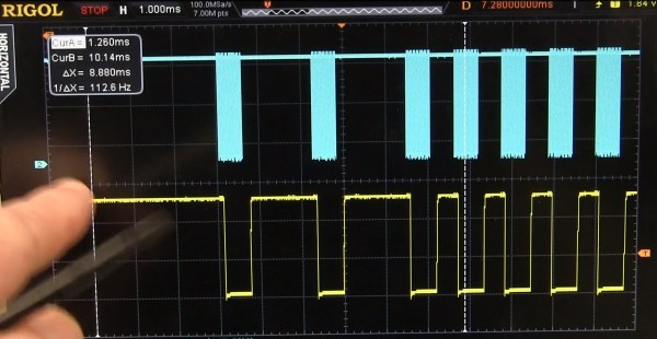
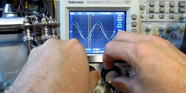
[Dave] needed a countdown timer that could remotely start and stop recording on his Cannon video camera, which he did with simplicity in a previous EEVBlog post using a commercial learning remote control unit. The fans demanded better so he delivered with this excellent tutorial capturing IR codes on his oscilloscope from an IR decoder (yellow trace) as well as using an IR photo transistor (blue trace) which showed the code inclusive of 38 KHz carrier frequency. Either capture method could easily be used to examine the transmitted code. The second lesson learned from the captured waveforms was the type of code modulation being used. [Dave’s] remote transmitted NEC (Japanese) pulse length encoding — which can be assertaind by referencing the Infrared Remote Control Techniques (PDF). Knowing the encoding methodology it was trivial to manually translate the bits for later use in an Arduino transmitter sketch. We find it amazing how simple [Dave] makes the process seem, even choosing to write his own sketch to reproduce and transmit the IR codes and carrier instead of taking the easy road looking for existing libraries.

A real gem of knowledge in the video was when it didn’t work! We get to follow along as [Dave] stumbles before using a Saleae Logic analyzer to see that his transmitter was off frequency even though the math in his sketch seemed correct. Realizing the digital write routine was causing a slowdown he fudged his math to make the needed frequency correction. Sure, he could have removed the performance glitch by writing some custom port control but logic dictates using the fastest and simplest solution when hacking a one-off solution.

[Dave’s] video and links to source code after the break.

Continue reading “Learn To Translate IR Codes And Retransmit Using Arduino”

Retrotechtacular: Fundamentals Of AM And FM Radio Communication

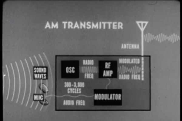
How radios send and receive information can seem magical to the uninformed. For some people, this week’s Retrotechtacular video, “Frequency Modulation – Part 1 Basic Principles”, from the US Army Department of Defense 1964 will be a great refresher, and for others it will be their first introduction into the wonderful world of radio communications.

The stated objective is to teach why FM radio communication reduces interference which normally afflicts AM radio communications. Fundamentals of AM and FM is a better description, however, because the first part of the video nicely teaches the principles of AM and FM radio communications. It isn’t until later in the clip that it delves into interference, advantages of FM modulation, and detailed functioning of FM radio. The delivery is slow at times and admittedly long, yet the pace is perfect for a young ham to follow along with plenty of time to soak in the knowledge. If you’re still on the fence about becoming a ham here’s some words or encouragement.

Though the video isn’t aimed at ham radio users it does address core knowledge needed by amateur radio hobbyists. Amateur radio is full of many exciting communication technologies and you should have a clear understanding of AM and FM communication methodologies before getting on Grandpa’s information super highway. Once you have your ham license (aka ticket) you have privileges to create and test amazing ham related hacks, like [Lior] implementing full programmable control of a Baofeng UV5R ham radio using an Arduino.

Join us after the break to watch the video.

Continue reading “Retrotechtacular: Fundamentals Of AM And FM Radio Communication”

DIY High Stability Timebase Hack For ~$25. Why? Frequency Stability Matters!

DIY High Stability Timebase OCXO

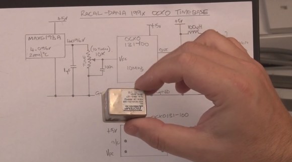
If you have an old “Racal-Dana 199x” frequency counter or similar 10 MHz internally referenced gear with a poor tolerance “standard quartz crystal oscillator” or bit better “temperature compensated crystal oscillator” (TCXO) you could upgrade to a high stability timebase “oven controlled crystal oscillator” (OCXO) for under $25. [Gerry Sweeney] shares his design and fabrication instructions for a DIY OCXO circuit he made for his Racal-Dana frequency counter. We have seen [Gerry] perform a similar upgrade to his HP 53151A, however, this circuit is more generic and can be lashed up on a small section of solderable perf board.

Oven controlled oscillators keep the crystal at a stable temperature which in turn improves frequency stability. Depending on where you’re starting, adding an OCXO could improve your frequency tolerance by 1 to 3 orders of magnitude. Sure, this isn’t as good as a rubidium frequency standard build like we have seen in the past, but as [Gerry] states it is nice to have a transportable standalone frequency counter that doesn’t have to be plugged into his rubidium frequency standard.

[Gerry’s] instructions, schematics and datasheets can be used to upgrade any lab gear which depends on a simple 10 MHz reference (crystal or TXCO). He purchased the OCXO off eBay for about $20 — it might be very old, yet we are assured they get more stable with age. Many OCXO’s require 5 V, 12 V or 24 V so your gear needs to accommodate the correct voltage and current load. To calibrate the OCXO you need a temperature stable variable voltage reference that can be adjusted from 1 to 4 volts. The MAX6198A he had on hand fit the bill at 5 ppm/°C temperature coefficient. Also of importance was to keep the voltage reference and trim pot just above the oven for added temperature stability as well as removing any heat transfer through the mounting screw.

You can watch the video and get more details after the break.

Continue reading “DIY High Stability Timebase Hack For ~$25. Why? Frequency Stability Matters!”

Homebuilt 30kV High Voltage Power Supply

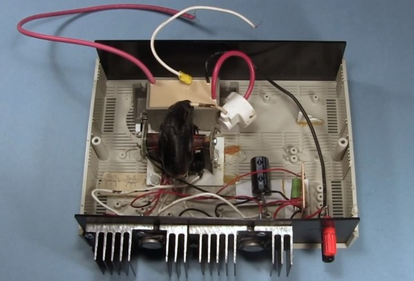
If you have need for 30,000 volts to launch your ionocraft (lifter) or power other DIY projects then shuttle over to RimstarOrg’s YouTube channel and checkout [Steven Dufresne’s] homebuilt 30kV power supply. The construction details that [Steven] includes in his videos are always amazing, especially for visual learners. If you prefer text over video he was kind enough to share a schematic and full write up at rimstar.org.

The power supply can be configured for 1.2kV – 4.6kV or 4kV – 30kV at the output while requiring 0-24V DC at the input. In the video [Steven] tries two power supplies. His homemade DC bench power supply at 8V and 2.5A and also a laptop power supply rated at 20V 1.8A DC. A couple of common 2N3055 power transistors, proper wattage resistors, a flyback transformer and a high voltage tripler is about all you’ll need to scrounge up. The flyback transformer can be found in old CRT type televisions, and he does go into details on rewinding the primary for this build. The high voltage tripler [Steven] references might be a bit harder to source. He lists a few alternates for the tripler but even those are scarce: NTE 521, Siemens 76-1 N094, 1895-641-045. There are lots of voltage multiplier details in the wild, but keep in mind this tripler needs to operate up to 30kV.

Join us after the break to watch the video and for a little advice from Mr. Safety.

Continue reading “Homebuilt 30kV High Voltage Power Supply”

Visually Tune Your HF Antenna Using An Oscilloscope And Signal Generator

Lots of readers are into toying around with RF and ham radios. One thing that is always of concern is tuning the antenna. New equipment is never cheap, so whenever another option comes along that uses existing test gear it gets our attention. [Alan Wolke] aka [w2aew] covers a process he uses to tune his HF antenna using a signal generator and oscilloscope.

The process is more of a teaching aid than a practical replacement for commercial equipment mostly because proper signal generators and oscilloscopes are large items and sometimes not available or affordable. That said, if you do have such test gear you only need build a simple breakout board containing a form of wheatstone bridge where the unknown Rx is the antenna. Two oscilloscope probes are connected across the bridge balance nodes. Some special care needs to be taken matching probe cable length and 50 ohm input impedance to the oscilloscope. A couple of 1K probe coupling resistors are also needed to prevent affecting the impendence at the hookup points. Once the selected signal is injected you can adjust an antenna tuner until the two voltage waveforms match on the oscilloscope indicating your antenna network is tuned to 50 ohm impedance with no reactance.

Being able to tune your antenna visually can really help you understand what is going on in the turning process; matching not only input impedance but also phase shift indicating inductive or capacitive reactance. Join us after the break to see the video and for information on what’s presented in the second part of [Alan’s] presentation.

Continue reading “Visually Tune Your HF Antenna Using An Oscilloscope And Signal Generator”

High Pressure Air Compressor Using A Pair Of Refrigeration Compressors

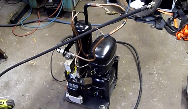
[Ed] from Ed’s Systems, aka [Aussie50] took some time to demo his high pressure Frankenstein air compressor he stitched together from two refrigeration compressors. The two Danfoss SC15 compressors can produce upwards of 400psi and can run all day at the 300 psi range without overheating. The dual units may get up to pressure quickly considering the small accumulator “tank”, but high CFM isn’t the goal with this build. [Ed] uses the system to massacre some LCD panels with lead, ball bearings, and other high speed projectiles shot from a modified sandblasting gun. Just a bit of air at 400 psi is all you need for this terminator toy.

Don’t think the destruction is wasteful either; [Ed] strives to repair, rebuild, reuse, repurpose and a few other R’s before carefully separating and sorting all the bits for recycling. This modification included lots of salvaged hardware from older teardowns such as high pressure hoses, connectors, accumulator and pressure cutoff switches.

At first it seems strange to see something engineered for R22 refrigerant working so well compressing air. Morphing refrigeration systems into air compressor service is something [Ed] has been doing for a long time. In older videos, “fail and succeed”,  [Ed] shows the ins and outs of building silent air compressors using higher capacity storage tanks. Being no stranger to all variations of domestic and commercial refrigeration systems, [Ed] keeps home built air compressors running safe and problem free for years.

Don’t think this is the only afterlife for old refrigeration compressors, we’ve seen them suck too. You’ll get a few more tidbits, and can watch [Ed’s] video overview of his home built compressor after the break.

Continue reading “High Pressure Air Compressor Using A Pair Of Refrigeration Compressors”

One Man’s Microwave Oven Is Another Man’s Hobby Electronics Store

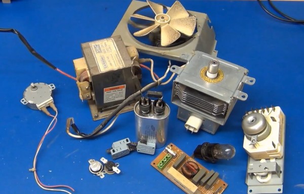
There are loads of Internet content depicting the usefulness of salvaged innards found in defunct microwave ovens. [Mads Nielsen] is an emerging new vblogger with promising filming skills and intriguing beginner electronics content. He doesn’t bring anything new from the microwave oven to the dinner table, yet this video should be considered a primer for anybody looking to salvage components for their hobby bench. To save some time you can link in at the 5 minute mark when the feast of parts is laid out on the table. The multitude of good usable parts in these microwave ovens rolling out on curbsides, in dumpsters, and cheap at yard sales all over the country is staggering and mostly free for the picking.

The harvest here was: micro switches, X and Y rated mains capacitors, 8 amp fuse, timer control with bell and switches, slow turn geared synchronous 4 watt motor 5 rpm, high voltage capacitor marked 2100 W VAC 0.95 uF, special diodes which aren’t so useful in hobby electronics, light bulb, common mode choke, 20 watt 68 Ohm ceramic wire-wound resistor, AC fan motor with fan and thermostat cutout switches NT101 (normally closed).

All this can be salvaged and more if you find newer discarded units. Our summary continues after the break where you can also watch the video where [Mads] flashes each treasure. His trinkets are rated at 220 V but if you live in a 110 V country such components will be rated for 110 V.

Continue reading “One Man’s Microwave Oven Is Another Man’s Hobby Electronics Store”