Don’t Wait, You Need To See Comet NEOWISE Right Now

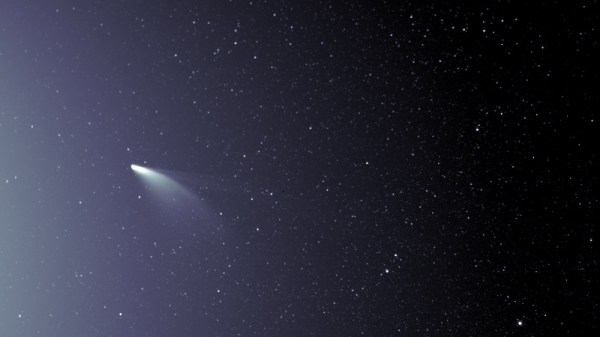
By now you’ve heard of NEOWISE, the most spectacular comet to visit our little corner of the galaxy since Hale-Bopp passed through over 20 years ago. But we’re willing to bet you haven’t actually seen it with your own eyes. That’s because up until now, the only way to view this interstellar traveler was to wake up in the pre-dawn hours; an especially difficult requirement considering a large chunk of the population has gotten used to sleeping-in over the last few months.

But things are about to change as NEOWISE begins a new phase of its trip through our celestial neck of the woods. Having come to within 44.5 million km (27.7 million miles) of the sun on July 3rd, the comet is now making its way back out of our solar system. Thanks to the complex dance of the heavens, that means that observers in the Northern Hemisphere will now be able to see NEOWISE in the evening sky just above the horizon.

NEOWISE is on a kind of “up and over” trajectory compared to the orbital paths of the planets. Get a better feel for it with JPL’s interactive solar dynamics tool.

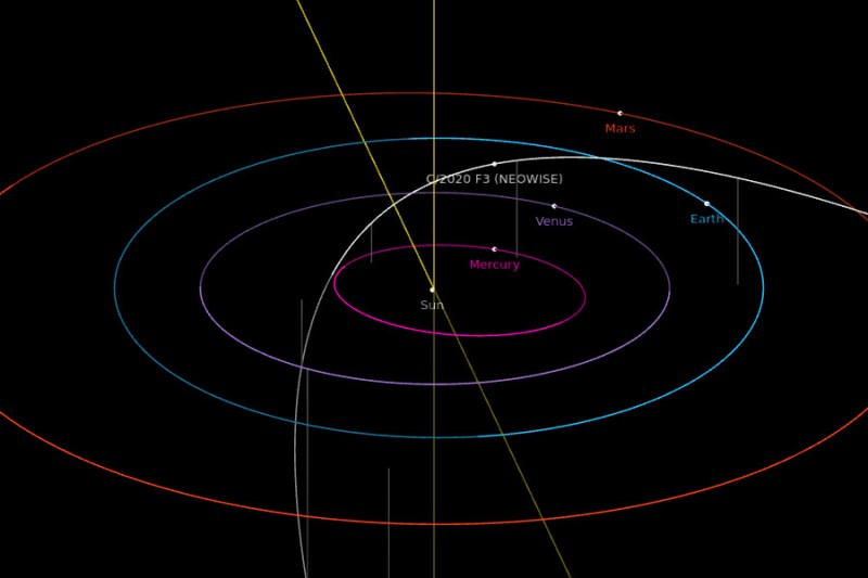
While NEOWISE might be beating a hasty retreat from Sol right now, the comet it actually getting closer to us in the process. On July 22nd it will reach perigee, that is, the point in its orbit closest to Earth. On that evening the comet will be approximately 103 million km (64 million miles) away. Not exactly a stone’s throw, but pretty close in astronomical terms. The comet will appear to be getting higher in the sky as it approaches Earth, and should be visible with the naked eye between 10 and 20 degrees above the northern horizon.

Most estimates say that NEOWISE should remain visible until at least the middle of August, though it will be dimming rapidly. After that, you’re going to have to wait awhile for a repeat showing. Given the orbit of this particular comet, it won’t come around our way again for approximately 6,800 years, give or take a few lifetimes.

NASA will be hosting a NEOWISE live stream tomorrow afternoon where researchers will answer questions about this once in a lifetime celestial event, though we think you’ll get a lot more out of it if you just go outside and look up.

Solar Weather Station Listens For Lightning

Custom weather stations are a common enough project these days, especially based around the ESP8266. Wire a sensor up to the MCU, power it up with an old phone charger, and you’re half way there. But if you want something that’s going to operate remotely on the long term, you’ve got to put a little more thought into it.

Which is exactly what [BuckarewBanzai] did for his solar powered Raspberry Pi weather station. With an industrial NEMA-rated enclosure, a beefy 35 watt photovoltaic panel, and enough lead-acid battery capacity to keep the show going for days, this build is certainly more robust than most. Some might call it overkill, but we think anyone who’s ever deployed hardware outdoors for more than a few days knows you can never be too careful when Mother Nature is involved.

To keep the 18 Ah battery topped off, [BuckarewBanzai] is using a 10 amp Wanderer charge controller. It sounds as though he burned through a few lesser models before settling on this one; something to consider for your own off-grid projects. An LM2596 regulator is then used to provide a stable 5 V for the Raspberry Pi.

In addition to the BME280 environmental sensor that picks up on temperature, humidity, and pressure, there’s also a AS3935 lightning sensor onboard which [BuckarewBanzai] says can pick up strikes up to 40 kilometers away. All of this environmental data is collected and stored in a local SQLite database, and gets pushed offsite every five minutes with a REST API so it can be visualized with Grafana.

Critics in the audience will no doubt pick up on the solderless breadboard located in the center of the weather station, but [BuckarewBanzai] says he’s already on the case. He’s working on a custom PCB that will accept the various modular components. Not only should this make the station more reliable, but he says it will cut down on the “spaghetti” wiring. Though for the record, this is hardly the worst offender we’ve seen in that department.

Printed TS100 Case Beats The Heat With A Bearing

As we’ve said many times in the past, the creation of custom cases and enclosures is one of the best and most obvious applications for desktop 3D printing. When armed with even an entry-level printer, your projects will never again have to suffer through the indignity of getting hot glued into a nondescript plastic box. But if you’re printing with basic PLA, you need to be careful that nothing gets too hot inside.

Which was a problem when [Oleg Vint] started work on this 3D printed case for the popular TS100 soldering iron. But with the addition of a standard 608 bearing, the case provides a safe spot for the iron to cool off before it gets buttoned back up for storage. Of course, you can also use the flip-out perch to hold the iron while you’re working.

The bearing stand that served as inspiration for the case.

As [Oleg] explains on the Thingiverse page for the case, he actually blended a few existing projects together to arrive at the final design. Specifically, the idea of using the 608 bearing came from a printable TS100 stand originally designed in 2017 by [MightyNozzle]. Released under Creative Commons, [Oleg] was able to mash the bearing stand together with elements from several other printable TS100 cases to come up with his unique combined solution.

In a physical sense, this project is a great example of the sort of bespoke creations that are made possible by desktop 3D printing. But it’s also a testament to the incredible community that’s sprung up around this technology. While the logistics of it still could use some work, seeing hackers and makers swap and combine their designs like this is extremely inspiring.

[Thanks Arturo182]

Life-Saving Surgery For A Telescopic Antenna

Whether it was as an impulsive youth or an impatient adult, there’s probably few among us who haven’t broken a telescopic antenna or two over the years. It doesn’t take much to put a bend in the thin walled tubing, and after that, all bets are off. So [The Amateur Engineer] couldn’t really be too upset when his son snapped the antenna off the transmitter of an old RC truck. Instead, he decided to take it apart and see how it could be repaired.

Taking a thin screwdriver to the antenna’s bottom most segment, he was able to widen up the opening enough to remove the upper sections as well as recover the broken piece and copper locking plates. He cut out the damaged area and drilled new holes for the pins on the copper plates to fit into. Inserting the repaired section back into the lowest segment was no problem, but he says it took a little trial and error before he was able to roll the edge over enough to keep the antenna from falling apart.

Buying a replacement would certainly have been easier, but as the radios in our devices have moved into the higher frequencies, these collapsible antennas have become a bit harder to come by. Modern RC vehicles operate on 2.4 GHz, so they don’t need the long antennas that the older 27 MHz systems utilized. [The Amateur Engineer] did find a few direct replacements online, but none for a price he was willing to pay.

We might have used the broken transmitter as an excuse to switch the RC vehicle over to WiFi control, but we appreciate [The Amateur Engineer] showing how this type of antenna can be disassembled and repaired if necessary.

Hacked Case Fan Follows The Leader With IR Sensor

Adding an additional fan to your PC is usually pretty straightforward, but as [Randy Elwin] found, this isn’t always the case with the newer Small Form Factor (SFF) machines. Not only was the standard 80 mm fan too large to fit inside of the case, but there wasn’t even a spot to plug it in. So he had to come up with his own way to power it up and control its speed.

Now if he only needed power, that wouldn’t have been a problem. You could certainly tap into one of the wires coming from the PSU and get 12 V to spin the fan. But that would mean it was running at max speed the whole time; fine in a pinch, but not exactly ideal for a daily driver.

Note the SATA connector pulled from a dead HDD.

To get speed control, [Randy] put together a little circuit using an ATtiny85, an IR LED, and a LTR-306 phototransistor. The optical components are used to detect the GPU fan’s current speed, which itself is controlled based on system temperature. Using the GPU fan RPM as an input, a lookup table on the microcontroller sets an appropriate speed for the 80 mm case fan.

One could argue that it would have been easier to connect a temperature sensor to the ATtiny85, but by synchronizing the case fan to the computer-controlled GPU fan, [Randy] is able to manually control them both from software if necessary. Rather than waiting on the case temperature to rise, he can peg the GPU fan and have the external fan speed up to match when the system is under heavy load.

You may think this is overkill for a simple case fan, but compared to some of the cooling hacks we’ve seen in the past, it’s pretty tame.

Steampunk Geiger Counter Is A Mix Of Art And Science

It took nearly a year for [Chris Crocker-White] to assemble this glorious mahogany and brass Geiger counter, but we think you’ll agree with us that it was time well spent. From the servo-actuated counter to the Nixie tubes and LED faux-decatrons, this project is an absolute love letter to antiquated methods of displaying information. Although for good measure, the internal Raspberry Pi also pushes all the collected radiation data into the cloud.

[Chris] says the design of this radiation monitor was influenced by his interest in steampunk and personal experience working on actual steam engines, but more specifically, he also drew inspiration from a counter built by [Richard Mudhar].

Based on a design published in Maplin back in 1987, [Richard] included a physical counter and LED “dekatron” displays as an homage to a 1960s era counter he’d used back in his school days. [Chris] put a modern spin on the electronics and added the glowing display of real-time Counts Per Minute (CPM) as an extra bonus; because who doesn’t like some Nixies in their steampunk?

Internally, the pulses generated by a common Geiger counter board are picked up by some custom electronics to drive the servo and LEDs. Triggered by those same pulses, the Raspberry Pi 3A+ updates the Nixie display and pushes the data out to the cloud for analysis and graphing. Note that the J305β Geiger tube from the detector has been relocated to the outside of the machine, with two copper elbows used as connectors. This improves the sensitivity of the instrument, but perhaps even more importantly, looks awesome.

We’ve seen some very high-tech DIY radiation detection gear over the years, but these clever machines that add a bit of whimsy to the otherwise mildly terrifying process of ionizing radiation are always our favorite.

Continue reading “Steampunk Geiger Counter Is A Mix Of Art And Science”

3D Printing A Macro Pad, Switches And All

Building a macro pad inside of a 3D printed enclosure is hardly news these days. Neither is adding 3D printed keycaps to the mix. But if you go as far as [James Stanley] has, and actually print the switches themselves, we’ve got to admit that’s another story entirely.

Now you might be wondering how [James] managed to print a mechanical keyboard switch that’s the size of your garden variety Cherry. Well, the simple answer is that he didn’t. While his printed switches have the same footprint as traditional switches, they are twice as tall.

The switches could probably made much smaller if it wasn’t for the printed spring, but using a “real” one would defeat the purpose. Though we do wonder if the mechanical design could be simplified by making it an optical switch.

But can printed switches really stand up to daily use? [James] wondered the same thing, so he built a testing rig that would hit the switches and count how many iterations before they stopped working. This testing seems to indicate that the keys will either fail quickly due to some mechanical defect, or last for hundreds of thousands of presses. So assuming you weed out the duds early, you should be in pretty good shape.

Naturally, there are a few bits of copper inside each printed switch to act as the actual contacts. But beyond that, all you need to build one of these printable pads yourself is a USB-HID capable microcontroller like the Arduino Pro Micro. If you used the ESP32, you could even make it Bluetooth.

Continue reading “3D Printing A Macro Pad, Switches And All”