Retrotechtacular: Apex Radio — The Forgotten HiFi

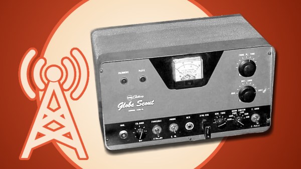
Broadcasting has changed a lot in the last few decades. We have satellite radio, internet streaming, HD radio all crowding out the traditional AM and FM bands. FM became popular because the wider channels and the modulation scheme allowed for less static and better sound reproduction. If you’ve never tried to listen to an AM radio station at night near a thunderstorm, you can’t appreciate how important that is. But did you know there was another U.S. broadcast band before FM that tried to solve the AM radio problem? You don’t hear about it much, but Apex or skyscraper radio appeared between 1937 and 1941 and then vanished with the onslaught of FM radio.

If you’ve heard of Apex radio — or if you are old enough to remember it — then you are probably done with this post. For everyone else, consider what radio looked like in 1936. The AM band had 96 channels between 550 and 1500 kHz. Because those frequencies propagate long distances at night, the FCC had a complex job of ensuring stations didn’t interfere with each other. Tricks like carefully choosing the location of stations, reducing power at night, or even shutting a station down after dark, were all used to control interference.

Continue reading “Retrotechtacular: Apex Radio — The Forgotten HiFi”

A Crystal Oscillator For A Stable Bench Reference

[Paul] likes a precise oscillator. His recent video shows a crystal oscillator with a “watch crystal” and a CMOS counter, the CD4060. Using such a circuit can produce very stable frequencies and since the 32.768 kHz crystal is a power of 2, you get nice divisions out of the counter.

We’ve seen the same trick done with decade counters (like the 4518B) to divide by 10 instead of powers of two to make frequency standards. A 1 MHz crystal can easily generate 100 kHz, 10 kHz, etc.

Continue reading “A Crystal Oscillator For A Stable Bench Reference”

Hands-On With New Arduino FPGA Board: MKR Vidor 4000

Hackaday brought you a first look the Arduino MKR Vidor 4000 when it announced. Arduino sent over one of the first boards so now we finally have our hands on one! It’s early and the documentation is still a bit sparse, but we did get it up and running to take the board through some hello world exercises. This article will go over what we’ve been able to figure out about the FPGA system so far to help get you up and running with the new hardware.

Continue reading “Hands-On With New Arduino FPGA Board: MKR Vidor 4000”

1950’s AM Transmitter Is Fun But Dangerous

[Mr. Carlson] bought a Globe Scout Model 40A ham radio transmitter at a hamfest. The 40A was a grand old transmitter full of tubes, high voltage, and a giant transformer. It is really interesting to see how much things have changed over the years. The transmitter is huge but has comparatively few parts. You needed a crystal for the frequency you wanted to talk. There were two little modules that were precursors to hybrid circuits (which were precursors to ICs) that were often called PECs or couplates (not couplets) but other than those, it is all tubes and discrete components beautifully wired point-to-point.

The really surprising part, though, is the back panel. There’s a screw terminal to drive the coil of an external coaxial relay that has line voltage on it. There’s also a plug on the back with exposed terminals that has plate voltage on it which is considerable. In the 1950s, you assumed people operating equipment like this would be careful not to touch exposed high voltage.

Continue reading “1950’s AM Transmitter Is Fun But Dangerous”

This Clock Is Hard: No Arduino Needed

You always hear that people talk about the weather. But it seems to us we see more clocks than we do weather stations. A case in point is [frank_scholl’s] clock made from an old hard drive. We found it interesting that the clock has no microcontroller at all. The custom PCB is all digital and uses the line frequency to drive counters which, in turn, drive the motors.

The one catch is that you have to have a hard drive that uses a very particular motor scheme for this to work. The platter rotation shows the hour and the head’s track position counts off the minutes from 0 to 59. Two buttons can speed up either rotation for the purpose of setting the clock. You can see it all in the video below.

Continue reading “This Clock Is Hard: No Arduino Needed”

Screaming Channels Attack RF Security

As long as there has been radio, people have wanted to eavesdrop on radio transmissions. In many cases, it is just a hobby activity like listening to a scanner or monitoring a local repeater. But in some cases, it is spy agencies or cyberhackers. [Giovanni Camurati] and his colleagues have been working on a slightly different way to attack Bluetooth radio communications using a technique that could apply to other radio types, too. The attack relies on the ubiquitous use of mixed-signal ICs to make cheap radios like Bluetooth dongles. They call it “Screaming Channels” and — in a nutshell — it is relying on digital information leaking out on the device’s radio signal.

Does it work? The team claims to have recovered an AES-128 key from 10 meters away. The technique reminds us a bit of TEMPEST in that unintended radio transmissions provide insight into the algorithm the device applies to encrypt or decrypt data. Most (if not all) encryption techniques assume you can’t see inside the “black box.” If you can, then it’s because it is relatively easy to break the code.

Continue reading “Screaming Channels Attack RF Security”

Circuit VR: An (Almost) Practical Buck Converter

In the last installment of Circuit VR, we walked around a simplified buck converter. The main simplification was using a constant PWM signal. The result is that the output voltage is a fixed fraction of the input voltage. For a regulator, the pulse width will need to depend on the output voltage so that any changes in the output are self-correcting. So this time, we’ll make a regulator, although we’ll still use a few Spice elements you’d have to replace in a practical design. In particular, we’ll assume you can generate a triangle wave, which is easy enough, and produce a stable 2.5 V reference.

The idea is to take a voltage reference and compare it to the output. We’ll think of the difference between the two as an error voltage, and use a comparator combined with a triangle wave generator to produce a PWM signal that is proportional to the error, and thus works to hold the output voltage constant.

Continue reading “Circuit VR: An (Almost) Practical Buck Converter”