Mad Eye For The WiFi

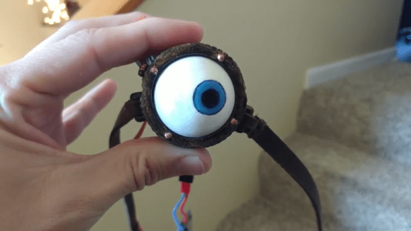
In the Harry Potter universe, Professor Moody was, perhaps unfairly, given the nickname Mad Eye for the prosthetic eye he wore. His eye remains a challenge for technically-minded cosplayers aiming to recreate the look and feel of this unique piece of headgear. [cyborgworkshop] had already mastered the basic eye, but wanted to take things further.

The original build relied on a sub-micro servo to move the eyeball. This was done at random as an attempt to simulate the eye’s behaviour in the books and films. However, wanting more, [cyborgworkshop] decided to make the eye more reactive to its surrounding environment. Using the Adafruit Huzzah, a breakout board for the ESP8266, code was whipped up to detect the number of WiFi access points in the area. The more access points, the more frequent and erratic the movement of the eye. Occasional slower periods of movement are coded in before the eye resumes its wild darting once more, depending on just how saturated the local WiFi environment is.

It’s a great twist on the project, and [cyborgworkshop] has provided more details on the initial build, too. If you think you’re having déja vu, check out this build using recycled parts.

Becoming Your Own ISP, Just For Fun

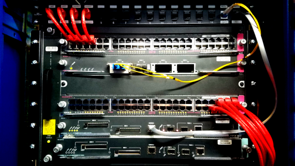
When moving into a new house, it’s important to arrange for the connection of basic utilities. Electricity, water, and gas are simple enough, and then it’s generally fairly easy to set up a connection to an ISP for your internet connection. A router plugs into a phone line, or maybe a fiber connection and lovely packets start flowing out of the wall. But if you’re connected to the internet through an ISP, how is the ISP connected? [Kenneth] answers this in the form of an amusing tale.

It was during the purchase of data centre rack space that [Kenneth]’s challenge was laid down by a friend. Rather then simply rely on the connection provided by the data centre, they would instead rely on forging their own connection to the ‘net, essentially becoming their own Internet Service Provider.

This is known as creating an Autonomous System. To do this involves several challenges, the first of which is understanding just how things work at this level of networking. [Kenneth] explains the vagaries of the Border Gateway Protocol, and why its neccessary to secure your own address space. There’s also an amusing discussion on the routing hardware required for such a feat and why [Kenneth]’s setup may fall over within the next two years or so.

It’s not for the faint hearted, and takes a fair bit of paperwork, but [Kenneth] has provided an excellent guide to the process if you really, really just need to own your own corner of the internet. That said, there are other networking tricks to cut your teeth on if you’d like a simpler challenge, like tunneling IP over ICMP.


Reverse Engineering The Nintendo Switch Joy-Cons

The Switch is Nintendo’s latest effort in the console world. One of its unique features is the Joy-Cons, a pair of controllers that can either attach directly to the console’s screen or be removed and used individually. But how do they work? [dekuNukem] decided to find out.

The reverse engineering efforts begin with disassembly. Surprisingly, there is no silkscreen present on the board to highlight test points or part numbers. This is likely to conflate intended to stymie community efforts to work with the hardware, as different teams may create their own designations for components. Conversely, the chips inside still have their identifying markings present, which does ease identification somewhat.

There are some interesting choices made – the majority of the buttons are scanned in a matrix configuration by the on-board microcontroller, making it harder to spoof button presses. The controllers communicate over Bluetooth, switching to a physical serial connection when attached directly to the screen. This runs at a blistering 3,125,000 BPS after the initial handshake is completed.

Overall it’s a fairly comprehensive reverse engineering effort, and [dekuNukem] has provided excellent detail in the writeup for anyone else looking to get involved. There’s still some work left to do, like investigating the rumble messages, but it’s an excellent start and very comprehensive.

Perhaps you’re more interested in older Nintendo hardware? Check out this comprehensive effort to figure out NES console-to-cartridge security methods.

Twin Pis For Remote Computer Management

Sometimes you have a whole bunch of computers that you need to work with, and having a keyboard, monitor, and mouse for each one becomes too much to deal with. There are a multitude of solutions to this problem, but [Fmstrat] went the hacker route, and built their own.

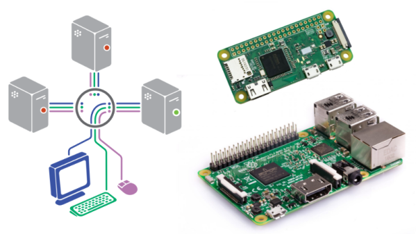
The build is a rather unique way of controlling PCs remotely, but it does the job. A Raspberry Pi 3 is pressed into service as the core of the operation. It’s accessible over IP for remote control. Video is captured from the controlled machines through the combination of an HDMI-to-S-Video adapter and an analog video capture card plugged into the Pi. Keystrokes are sent in a roundabout way, first sent to a Pi Zero over a USB-to-Serial adapter. From there, the Pi acts as an emulated mouse and keyboard to the PC under control.

One caveat of remotely controlling computers over a network is that if things go pearshaped, it can become necessary to power cycle the machine. [Fmstrat] deals with this by fitting a relay board to the Pi 3, which is connected to the reset buttons of the machines under control.

It may not be the quickest, easiest, or industry standard way of controlling remote computers, but it works. [Fmstrat] tells us this build was primarily designed to get around the fact that there aren’t any decent cheap IP-KVM systems, and consumer motherboards don’t support the IPMI standard that would otherwise be useful here.

We particularly like the hard-wired relays for rebooting a machine – great for when a network dropout is stopping Wake-on-LAN packets from achieving their goal. While the conversion of HDMI outputs into analog video for capture is unusual and somewhat costly on a per-machine basis, it’s functional and gives the system the ability to work with any machine capable of outputting a basic analog video signal. With the Pi Zero keyboard emulation and analog video capture, we could see this being used with everything from modern computers to vintage 80s hardware. If you’ve ever needed to control an Amiga 2000 remotely for whatever reason, this could be the way to do it.

We’ve seen plenty of other KVM builds over the years, too – like this low-cost HDMI switcher.

386 Too Much Horsepower? Try A 186, In An FPGA!

Typically when we hear the term “System-on-Chip” bandied around, our mind jumps straight to modern ARM-based processors that drive smartphones and embedded devices around us. Coming a little bit more out of left field is [Jamie]’s 80186 core, that runs on Intel FPGAs.

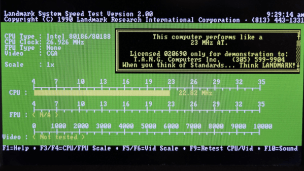
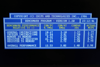
[Jamie] ran the core through a few vintage PC benchmarks.
[Jamie] has implemented the entire set of 80186 instructions in Verilog, and included some of the undocumented instructions too. This sort of attention to detail is important – real world parts don’t always meet the original specifications on paper, and programmers can come to rely on this. The key to compatibility is understanding how things perform in the real world, not just on the spec sheet.

Not content to simply simulate a CPU, all the necessary peripherals for a complete working system have been worked into the design as well. There’s RAM, a UART, as well as CGA graphics and a PS/2 controller that is necessary if you’d like to actually use any sort of human input device.

[Jamie] has released the code under a GPL licence, and it’s available at GitHub. It’s a good basis if you want to play around with what was once a commercial CPU at a logic level. The development guide is also available if you need to really drill down into the details. It’s a cool project, and makes a great contrast to [Jamie]’s previous work – the Oldland 32-bit core.


Finally – A Big-Screen Vectrex

The Vectrex is in no way the most popular console of all time, but it is one of the more unique. Eschewing typical raster-based rendering, it instead relies on a vector-based display. Since the average home television of the era would be completely unable to display such signals, the Vectrex had its screen built in. This got [Arcade Jason] wondering – would it be possible to hook the Vectrex up to a bigger screen?

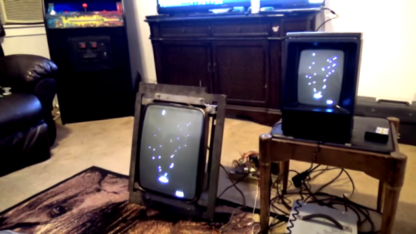
First, a suitable monitor had to be found. The 19V2000 turned out to be a good candidate – much larger at 19 inches, and found in a variety of arcade cabinets from years past. From there, the project became a matter of identifying the signal outputs of the Vectrex. [Arcade Jason] took the liberty of modifying the levels of the signals on the Vectrex board itself, and then fixing the now-overscanned image on the original screen by adjusting the onboard trimpots. With the Vectrex’s X and Y signals now boosted somewhat, they were wired up to the inputs of the larger arcade screen. For the Z signal, things got even hackier – a Walmart “Computer Amplifier”, typically used for speakers, was instead pressed in to service to amplify the signal.

There are plenty of wires running all over the carpet in this video, but the fact is, it works brilliantly. Future plans involve upgrading to an even larger 23 inch monitor, and possibly even experiments with color vector displays. It just goes to show that the Vectrex, even today, maintains a die-hard following.

Perhaps you’d like to try this, but need to fix your original Vectrex screen first? Never fear – that’s possible, too.


Pi Handheld With A Mindblowing Enclosure

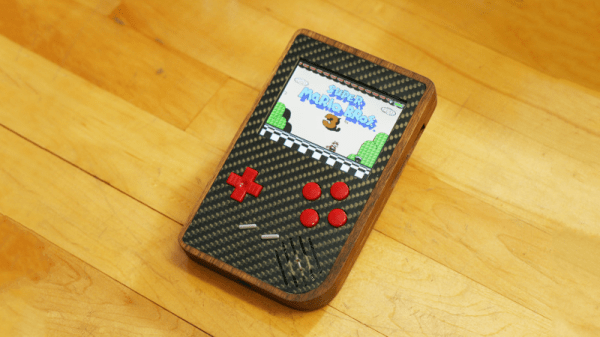
The Raspberry Pi is possibly the world’s most popular emulation platform these days. While it was never intended to serve this purpose, the fact remains that a small, compact computer with flexible I/O is ideally suited to it. We’ve featured a multitude of builds over the years using a Pi in a mobile form factor to take games on the go. [Michael]’s build, however, offers a lot more than a few Nintendo ROMs and some buttons from eBay. It’s a tour de force in enclosure design.

The build starts with the electronics. In 2017 it’s no longer necessary to cobble together five different accessory boards to handle the controls, battery charging, and display. Boards like Kite’s Super All In One exist, handling everything necessary for a handheld game console. With this as a starting point, he then set out to recreate Nintendo’s classic Game Boy, with a few tweaks to form and function.

It’s a textbook example of smart planning, design, and execution. We are taken through the process of creating the initial CAD drawings, then combining 3D printed parts with wood and carbon fibre for a look that is more akin to a high-end piece of hi-fi gear than anything related to gaming. The attention to detail is superb and the write-up makes it look easy, while [Michael] shares tips on how to safely cut carbon fibre to make your own buttons.

The final results are stunning, and it’s a great example of why a fine piece of wood is always a classy way to go for an enclosure. For another great example, try this walnut keyboard, or check out the roots of the Raspberry Pi Game Boy movement.