Many in the community are skeptical about the security of commercial smart home devices, and for good reason. It’s not like you have to look far to find examples of poorly implemented systems, or products that are abandoned by their manufacturers and left without critical security updates. But the design flaw in this video doorbell really drives home how little thought some companies give to their customer’s security.
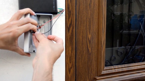
 As explained by [Savvas], and demonstrated in the video after the break, all you need to do if you want to get into a home equipped with one of these vulnerable door bells is pop the unit off the wall and hit it with 12 volts DC.
Incredibly, the terminals that connect to the electronic lock inside the house are completely accessible on the back of the unit. They even labeled them, on the off-chance the robber forgets which wire is which. It’s not even as though the thing is held on with some kind of weird security screws, it’s just a garden variety Phillips.
In the video, [Savvas] even shows he used a little gadget attached to a QuickCharge USB battery bank to get a portable 12 VDC source suitable for tripping these locks. Which, interestingly enough, is based on a trick he read about in the Hackaday comments. Something to consider while penning your next comment on these storied pages.
[Savvas] says he’s reached out to the company to get their side of the story, but so far, hasn’t received a response. We aren’t surprised, this is a fundamental flaw in the product’s execution. Clearly they wanted to make an easy to install device that doesn’t require any additional electronics in the house, and this is the inevitable end result of that oversimplification. All the more reason to roll your own smart doorbell.
Continue reading “Pop Open Your Neighbor’s Front Door With 12 Volts”