Escape Cable Hell With An Audio I/O Multiplexer

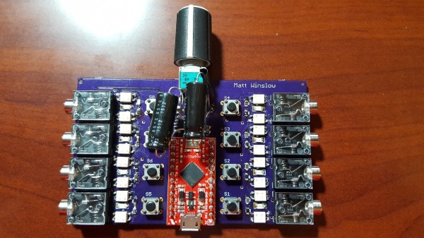
If you ever find yourself swapping between a mix of audio inputs and outputs and get tired of plugging cables all the time, check out [winslomb]’s audio multiplexer with integrated amplifier. The device can take any one of four audio inputs, pass the signal through an amplifier, and send it to any one of four outputs.

The audio amplifier has a volume control, and the inputs and outputs can be selected via button presses. An Arduino Pro Mini takes care of switching the relays based on the button presses. On the input side, you can plug in devices like a phone, TV, digital audio player or a computer. The output can be fed to speakers, headsets or earphones.

At the center of the build lies a TI TPA152 75-mW stereo audio power amplifier. This audio op-amp is designed to drive 32 ohm loads, so performance might suffer when connecting it to lower impedance devices, but it seems to work fine for headphones and small computer speakers. The dual-gang potentiometer controls the volume, and the chip has a useful de-pop feature. The circuit is pretty much a copy of the reference shown in the data sheet. Switching between inputs or outputs is handled by a bank of TLP172A solid state relays with MOSFET outputs, and it’s all tied together with a micro-controller, allowing for WiFi or BLE functionality to be added on later.

[winslomb] laid out the design using Eagle and he made a couple of footprint mistakes for the large capacitors and the opto-relays. (As he says, always double-check part footprints!) In the end, he solder-bridged them on to the board, but they should probably be fixed for the next revision.

[winslomb] built the switch as his capstone project while on his way to getting a Masters in EE, and although the device did function as required, there is still room for improvement. The GitHub repository contains all the hardware and software sources. Check out the video below where he walks through a demo of the device in action. If you are looking for something simpler, here is a two input – one output audio switcher with USB control and on the other end of the spectrum, here’s an audio switch that connects to the Internet.

Continue reading “Escape Cable Hell With An Audio I/O Multiplexer”

Arduino Analog I/O Multiplexer

[SeanHodgins] has a project in mind where he needs to sample over 500 analog sensors. To get ready, he made a breakout board for 32-channel analog multiplexer device he wants to use. He put the project out on Hackaday.io and also has a video tutorial you can see below.

There are five input pins to the chip which lets you connect one analog pin to any one of 32 analog pins. Of course, in addition to the five control lines, you need some handshaking lines, too so you could use as many as eight digital pins to control the device.

Continue reading “Arduino Analog I/O Multiplexer”

Tiny Audio Switcher Eliminates Repetitive Plug Swapping

usb-audio-switcher

[Phil] uses both his computer’s speakers and a set of headphones while working at his desk, but he was growing tired of constantly having to remove the headset from his sound card in order to insert the speaker plug. He’s been meaning to rig something up to make it easier to switch outputs, but never seemed to get around to it until he recently saw this LAN-enabled audio switcher we featured.

His USB-controlled switch features a single audio input and two audio outputs, which he mounted on a nicely done homemade double-sided PCB. The switch can be toggled using any terminal program, sending commands to the on-board ATtiny13A via an FT232R USB to serial UART chip.

The switch’s operation is really quite simple, merely requiring [Phil] to type in the desired audio channel into the terminal. The ATiny and a small relay do the rest, directing the audio to the proper output.

Hackaday Podcast 146: Dueling Trackballs, Next Level BEAM Robot, Take Control Of Your Bench, And Green Programming

Postpone your holiday shopping and spend some quality time with editors Mike Szczys and Elliot Williams as they sift through the week in Hackaday. Which programming language is the greenest? How many trackballs can a mouse possibly have? And can a Bluetooth dongle run DOOM? Join us to find out!


Take a look at the links below if you want to follow along, and as always, tell us what you think about this episode in the comments!

Direct download (52 MB)

Continue reading “Hackaday Podcast 146: Dueling Trackballs, Next Level BEAM Robot, Take Control Of Your Bench, And Green Programming”

How To Modify Your Car Stereo For Bluetooth Or Aux-In

If you’re an automotive enthusiast of taste, you can’t stand the idea of fitting a janky aftermarket stereo into your nice, clean ride. Flashy, modern head units can spoil the look of a car’s interior, particularly if the car is a retro, classic, or vintage ride.

Thus, we’re going to look at how to modify your existing stock car stereo to accept an auxiliary cable input or even a Bluetooth module. This way, you can pump in the latest tunes from your smartphone without a fuss, while still maintaining an all-original look on the dash.

Fundamentals

A simple Bluetooth module designed for wiring into car audio systems. There are two wires for 12 V power from the vehicle, and the audio signal is sent out over the RCA plugs. The RCA plugs can be cut off and the module hard wired inside your stereo if you have room. Cutting off the plastic case can help too.

Depending on your choice of audio player, you may prefer a 3.5 mm aux jack, or you might want to go with Bluetooth audio if your smartphone no longer has a headphone port. Whichever way you go, the process of modifying the stereo is largely the same. To achieve your goal, you need to find a way of injecting the audio signal into the head unit’s amplifier stage, while making sure no other audio sources are getting sent there as well.

Whether that audio source is a 3.5 mm jack or a Bluetooth module doesn’t matter. The only difference is, in the latter case, you’ll want to buy a Bluetooth module and hardwire it in to the auxiliary input you create, while also splicing the module into the stereo’s power supply. In the case of a simple headphone jack input, you simply need to wire up an aux cord or 3.5 mm jack somewhere you can get to it, and call it done.

This guide won’t cover every stereo under the sun, of course. Edge cases exist and depending on the minute specifics of how your original car radio works, these exact methods may or may not work for you. However, this guide is intended to get you thinking conceptually about how such mods are done, so that you can investigate the hardware in front of you and make your own decisions about how to integrate an external audio input that suits your usage case. Continue reading “How To Modify Your Car Stereo For Bluetooth Or Aux-In”

Custom Built 12-Port A/V Switch Keeps CRT Well Fed

Classic gaming aficionados who prefer to play on real hardware know the struggle of getting their decades-old consoles connected to a modern TV. Which is why many gamers chose to keep a contemporary CRT TV around for when they want to take a walk down memory lane. Unfortunately those old TVs usually didn’t offer more than a few A/V ports on the back, so you’ll probably need to invest in a A/V switch to keep them all hooked up at once.

That’s the situation [Thomas Sowell] found himself in, except he couldn’t find one with enough ports. Rather than chain switches together, he decided to build his own custom 12-port console selector. With an integrated amplifier to keep everything looking sharp, a handsome walnut and metal enclosure, and a slick graphical interface that shows the logo of the currently selected console on a Vacuum Fluorescent Display (VFD), the final product is a classic gamer’s dream come true.

A peek under the hood.

To switch the audio [Thomas] is using a pair of ADG1606 16-channel analog multiplexers, while video is shuffled around with four MAX4315 8-channel video multiplexer-amplifiers. The math might seem a bit off at first, but he’s using one ADG1606 for each stereo channel and since the switch is for S-Video, each device has a luminance and color signal that needs to be handled separately. The multiplexers are flipped with a ATmega2561 microcontroller, which is also responsible for reading user input from a rotary encoder on the front of the case and displaying the appropriate console logo on the 140×32 Noritake VFD.

You may be surprised to find that [Thomas] considered himself an electronics beginner when he started this project, and that this is only the second PCB he’s ever designed. Was this a bold second project? Sure. But it also speaks to how far DIY electronics has come over the last years. Powerful open source tools, modular components, and of course a community of creative folks willing to share their knowledge and designs, has gone a long way towards redefining whats possible for the individual hacker and maker.

Continue reading “Custom Built 12-Port A/V Switch Keeps CRT Well Fed”

Smart Station Runs Entertainment, Is Entertainment

It’s that special time of year—time for the parade of student projects from [Bruce Land]’s embedded microcontroller design course at Cornell. [Timothy], [Dhruv], and [Shaurya] are all into remote sensing and control applications, so they built a smart station that combines audiovisual entertainment with environmental sensing.

As with the other projects in this course, the smart station is built on a PIC32 dev board. It does Bluetooth audio playback via RN-52 module and has a beat-matching light show in the form of a NeoPixel ring mounted atop the 3D-printed enclosure. But those blinkenlights aren’t just there to party. They also provide visual feedback about the environment, which comes from user-adjustable high and low trigger values for the mic, an accelerometer, a temperature and humidity sensor, and a luminosity sensor.

The group wanted to add an ultrasonic wake-up feature, but it refused to work with the 3.3V from the PIC. The NeoPixel ring wanted 5V too, but isn’t as picky. It looks to be plenty bright at 3.3V. Another challenge came from combining I²C, UART, analog inputs, and digital outputs. They had to go to the chip’s errata to verify it, but it’s there: whenever I²C1 is enabled, the first two analog pins are compromised, and there’s no official solution. The team got around it by using a single analog pin and a multiplexer. You can check out those blinkenlights after the break.

Maybe you prefer working in wood. If so, you might like this hexagonal take on audio-visualization.

Continue reading “Smart Station Runs Entertainment, Is Entertainment”