If you’re lucky, reverse engineering can be a messy business. Sure, there’s something to be said for attacking and characterizing an unknown system and leaving no trace of having been there, but there’s something viscerally satisfying about destroying something to understand it. Especially when homemade fuming nitric acid is involved.
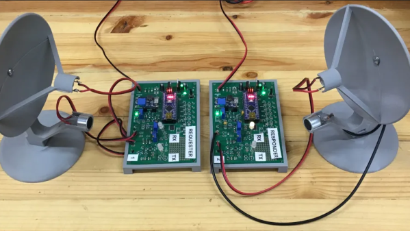
The recipient of such physical and chemical rough love in the video below is a residential electric smart meter, a topic that seems to be endlessly fascinating to [Hash]; this is far from the first time we’ve seen him take a deep dive into these devices. His efforts are usually a little less destructive, though, and his write-ups tend to concentrate more on snooping into the radio signals these meters are using to talk back to the utility company.
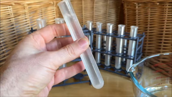
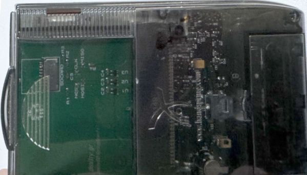
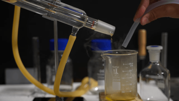
This time around, [Hash] has decided to share some of his methods for getting at these secrets, including decapping the ICs inside. His method for making fuming nitric acid from stump remover and battery acid is pretty interesting; although the laboratory glassware needed to condense the FNA approaches the cost of just buying the stuff outright, it’s always nice to have the knowledge and the tools to make your own. Just make sure to be careful about it — the fumes are incredibly toxic. Also detailed is a 3D-printable micropositioner, used for examining and photographing acid-decapped ICs under the microscope, which we’d bet would be handy for plenty of other microscopy jobs.
In addition to the decapping stuff, and a little gratuitous destruction with nitric acid, [Hash] takes a look at the comparative anatomy of smart meters. The tamper-proofing features are particularly interesting; who knew these meters have what amounts to the same thing as a pinball machine’s tilt switch onboard?
Continue reading “Reverse Engineering Smart Meters, Now With More Fuming Nitric Acid”