This week, Hackaday Editor-in-Chief Elliot Williams and Assignments Editor Kristina Panos fawn over a beautiful Italian split-flap clock that doesn’t come cheap, and another clock made of floppies that could be re-created for next to nothing. We’ll also sing the praises of solderless circuitry for prototyping and marvel over a filament dry box with enough sensors to control an entire house. The finer points of the ooh, sparkly-ness of diffraction gratings will be discussed, and by the end of the show, you’ll know what we each like in a microscope.
Take a look at the links below if you want to follow along, and as always, tell us what you think about this episode in the comments!
(And if you’re wondering about what my joke about not having Kristina on the show for 28 seconds, and all the professionalism, was about — we both forgot to press record the first time through and got ~15 minutes into the show before noticing. Yeah. But we had a good time the second time around anyway.)
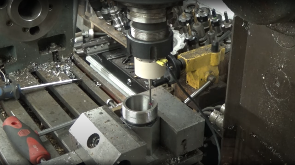
Millimeter-wave Radars used in modern cars for cruise control and collision avoidance are usually designed to work at ranges on the order of 100 meters or so. With some engineering nous, however, experimenters have gotten these devices sending signals over ranges of up to 60 km in some tests. [Machining and Microwaves] decided to see if he could push the boat out even further, and set out machining some waveguide combiner cavities so he could use the radar chips with some very high-performance antennas.
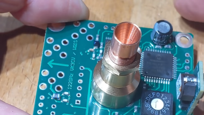
Precision-machined components are required to successfully use these 122 GHz components for long-range transmissions.
The end goal of the project is to produce a 53 dBi antenna for the 122GHz signal put out by the mmWave radar chips commonly found in automotive applications. Working at this frequency requires getting tolerances just so in order to create an antenna that performs well.
Plenty of fine lathe work and cheerful machining banter later, and the precision waveguide is done. It may not look like much to the untrained eye, but much careful design and machining went on to make it both easy to attach to the radar and parabolic antenna system, and to make it perform at a high enough level to hopefully break records set by other enterprising radio experimenters. If that wasn’t all hard enough, though, the final job involved making 24 of these things!
There aren’t a whole lot of microwave antenna-specific machining channels on YouTube, so if you’ve been thirsty for that kind of content, this video is very much for you. If you’re more interested in antennas for lower frequencies, though, you might find some of our other stories to your liking. Video after the break.
It’s an age-old riddle: if you have a perfect sphere with a perfectly reflective inner surface, will light bounce around inside it forever? The answer is pretty obvious when you think it through, but that doesn’t mean that you can’t put the principle to use, as we see with this homemade Ulbricht sphere for optical measurements.
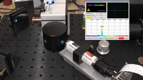
If you’ve never heard of an Ulbricht sphere, don’t worry — it’s also known as an integrating sphere, and that makes its function a little more apparent. As [Les Wright] explains, an integrating sphere is an optical element with a hollow spherical cavity that’s coated with a diffusely reflective coating. There are two ports in the sphere, one for admitting light — usually from a laser — and one for light to exit. The light bounces around inside the sphere and becomes perfectly diffuse, and creates a uniform beam at the exit port.
[Les]’ need for an integrating sphere comes from the desire to measure the output of some of his lasers with his Raspberry Pi-based PySpectrometer. Rather than shell out for an expensive commercial integrating sphere, or turn one on a lathe, [Les] turned to an unlikely source: cannonball molds. The inside of the mold was painted with an equally unlikely ultra-white paint concocted from barium sulfate and PVA glue. With a few ports machined into the mold, it works perfectly to diffuse the light from his dye lasers for proper measurements.
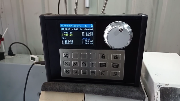
An electronic leadscrew is an increasingly popular project for small and mid-sized lathes. They do away with the need to swap gears in and out to achieve the proper ratio between spindle speed and tool carriage translation, and that makes threading a snap. But well-designed electronic leadscrews, like this one from [Hobby Machinist], offer so much more than just easy threading.
The first thing that struck us about this build was the polished, professional look of it. The enclosure for the Nucleo-64 dev board sports a nice TFT display and an IP65-rated keyboard, as well as a beefy-looking jog wheel. The spindle speed is monitored by a 600 pulses-per-revolution optical encoder, and the lathe’s leadscrew is powered by a closed-loop NEMA 24 stepper. This combination allows for the basic threading operations, but the addition of a powered cross slide opens up a ton more functionality. Internal and external tapers are a few keypresses away, as are boring and turning and radius operations, both on the right and on the left. The video below shows radius-cutting operations combined to turn a sphere.
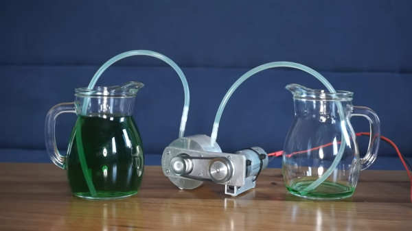
The peristaltic pump is perhaps most well known for its ability to pump fluids without the pump mechanism coming into contact with the working fluid. This is key for food-safe applications and other situations where a pump could contaminate the fluid. [Maciej Nowak] has built a great example of such a pump, crafted out of aluminium from scratch.
The build video covers the machining process in detail, showing how the aluminium body was fabricated on the lathe before installing bearings and a silicone hose. The pump shaft was then fabricated, along with a set of brass rollers to press along the tube, creating the pumping action. The rollers were also lubricated in order to reduce friction on the tubing. Powering the pump is a small DC motor, sending drive via a small toothed belt, giving the finished build quite an industrial look.
We’re used to seeing plenty of 3D-printed pumpsabout the place. This build, while it requires a fully-equipped machine shop, is much tougher than anything plastic, and you could easily use it to break a window in an emergency too, an obscure feature nevertheless requested by some discerning pump customers.
[Maciej] shows off the build by pumping some green liquid, noting the peristaltic design requires no priming which makes operation much easier. It’s also bidirectional, and can be run very slowly if required.
Overall, it’s a build that shows off the benefits of working in metal as well as the great features of the peristaltic pump design. Video after the break.
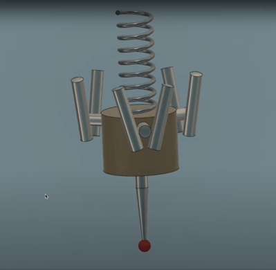
LinuxCNC contributor and machining enthusiast [Andy Pugh] is certainly not afraid to try making specialised tools to see how well they work out, and this time he’s been busy making a touch probe (video, embedded below) for checking the accuracy of machining operations and general measuring applications.
These things are not cheap, since they are essentially ‘just’ a switch with a long probe, But, as with anything specialised and machined with tight tolerances, you can understand why they cost what they do.
After inspecting and spending some time reverse-engineering such a unit, [Andy] then proceeded to grab some PEEK bar he had lying around and chuck it into the lathe (get it?). He notes Delrin would be more cost effective for those wishing to reproduce this, but as long as you have the ability to machine it and it’s non-conductive, there are many other options you could try.
Using no special tools other than a collet block (like this one) all the angled holes and slots were made with ease, with the help of a specially 3D-printed mount for the vise. A nice, simple approach, we think!
[Andy] tested the repeatability of the probe, mounted over his CNC-converted Holbrook lathe, reporting a value of 1 um, which seems rather good. Centering of the probe tip within the probe body was off a bit, as you’d expect for something made practically by hand, but that is less of a problem as it would seem, as it results in a fixed offset that can be compensated for in software. Perhaps the next version will have some adjustability to dial that out manually?
The whole assembly is formed from two plastic parts, a handful of ground-finished hardened steel pins, and a big spring. The only part remotely special is an off-the-shelf probe tip. During the electrical hookup, you may notice the use of a self-fluxing verowire pen, which was something this scribe didn’t know existed and has already placed an order for!
The reference 3D model for the design is shared from [Andy]’s Autodesk Drive for your viewing pleasure.
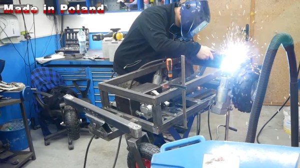
Have you ever looked at a derelict electric wheelchair and thought “I bet I could make something great with that!” Of course you have- this is Hackaday, after all! And so did [Made in Poland], who managed to get a hold of a broken down electric wheelchair and put the full utility of his well equipped metalworking shop to work. The results? Lets just say it hauls.
What we really enjoyed about the build was that there wasn’t much that couldn’t be done by an average garage hacker with a drill press, angle grinder, and a stick welder. While it’s definitely nicer to have a lathe and a high quality welding table, plasma cutter, and everything in between, nothing that [Made in Poland] did in the video is such high precision that it would require those extensive tools. There may be some parts that would be a lot more difficult, or lower precision, but still functional.
Another aspect of the build is of course the control circuitry and user interface. Keeping the skid steer and castor approach meant that each motor would need to be controllable independently. To achieve this, [Made in Poland] put together a purely electromechanical drive controlled with momentary rocker switches and automotive relays to form a simple H-Bridge for each motor.
Of course you just have to watch until the end, because it really proves that a man will do anything to get out of hauling wood around! Old electric wheelchairs can also make a great base for big robots, as it turns out.