Review: WAINLUX K8, A Diode Laser That’s Ready To Work

Rarely a week goes by that some company doesn’t offer to send us their latest and greatest laser. You know the type — couple of aluminum extrusions, Class 4 diode flopping around in the breeze, and no enclosure to speak of unless you count the cardboard box they shipped it in. In other words, an accident waiting to happen. Such gracious invitations get sent to the trash without a second thought.

Now don’t get me wrong, I have no doubt that the average Hackaday reader would be able to render such a contraption (relatively) safe for use around the shop. Build a box around it, bolt on a powerful enough fan to suck the smoke out through the window, and you’ve turned a liability into a legitimate tool. But the fact remains that we simply can’t put our stamp on something that is designed with such a blatant disregard for basic safety principles.

The earlier WAINLUX JL4 — lucky rabbit foot not included.

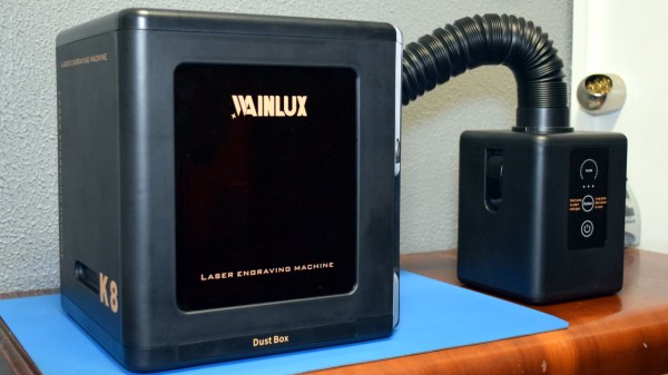
That being the case, a recent email from WAINLUX nearly met the same fate as all those other invitations. But even at a glance it was clear that this new machine they wanted to send out, the K8, was very different from others we’d seen. Different even from what the company themselves have put out to this point. This model was fully enclosed, had a built-in ventilation fan, an optional air filter “sidecar”, and yes, it would even turn off the laser if you opened the door while it was in operation. After reading through the promotional material they sent over, I had to admit, I was intrigued.

It seemed like I wasn’t the only one either; it was only a matter of days before the Kickstarter for the WAINLUX K8 rocketed to six figures. At the time of this writing, the total raised stands at just under $230,000 USD. There’s clearly a demand for this sort of desktop laser, the simplicity of using a diode over a laser tube is already appealing, but one that you could actually use in a home with kids or pets would be a game changer for many people.

But would the reality live up to the hype? I’ve spent the last couple of weeks putting a pre-production WAINLUX K8 through its paces, so let’s take a look and see if WAINLUX has a winner on their hands.

Continue reading “Review: WAINLUX K8, A Diode Laser That’s Ready To Work”

Cutting Metals With A Diode Laser?

Hobbyist-grade laser cutters can be a little restrictive as to the types and thicknesses of materials that they can cut. We’re usually talking about CO2 and diode-based machines here, and if you want to cut non-plastic sheets, you’re usually going to be looking towards natural materials such as leather, fabrics, and thin wood.

But what about metals? It’s a common beginner’s question, often asked with a resigned look, that they already know the answer is going to be a hard “no. ” However, YouTuber [Chad] decided to respond to some comments about the possibility of cutting metal sheets using a high-power diode laser, with a simple experiment to actually determine what the limits actually are.

Using an XTool D1 Pro 20W as a testbed, [Chad] tried a variety of materials including mild steel, stainless, aluminium, and brass sheets at a variety of thicknesses. Steel shim sheets in thicknesses from one to eight-thousandths of an inch appeared to be perfectly cuttable, with an appropriate air assist and speed settings, with thicker sheets needing a good few passes. You can definitely see the effect of excess heat in the workpiece, resulting in some discoloration and noticeable warping, but those issues can be mitigated. Copper and aluminium weren’t touched by the beam at all, likely due to the extra reflectivity, but we do have to wonder if appropriate surface treatments could improve matters.

Obviously, we’ve seen that diode lasers can have an impact on metals, simply smearing a little mustard on the workpiece seems to make marking a snap. Whilst we’re on the subject of diode lasers, you can get a lot of mileage from just strapping such a laser module onto a desktop CNC.

Continue reading “Cutting Metals With A Diode Laser?”

An array of tiny parallel green lines appears over a steel surface. The white dot a laser beam is visible in the lower center of the picture.

A New Way To Make (Almost) Holograms With Lasers

The spectrum of laser technologies available to hackers has gradually widened from basic gas lasers through CO2 tubes, diode lasers, and now fiber lasers. One of the newer entries is the MOPA laser, which combines a laser diode with a fiber-based light amplifier. The diode’s pulse length and repetition rate are easy to control, while the fiber amplifier gives it enough power to do interesting things – including, as [Ben Krasnow] found, etch hologram-like diffraction gratings onto stainless steel.

Stainless steel works because it forms a thin oxide layer when heated, with a thickness determined by the temperature it reaches. The oxide layer creates thin-film interference with incoming light, letting the laser mark parts of a steel sheet with different colors by varying the intensity of heating. [Ben] wrote a script to etch color images onto steel using this method, and noticed in one experiment that one area seemed to produce diffraction patterns. More experimentation revealed that the laser could consistently make diffraction gratings out of parallel patterns of oxide lines. Surprisingly, the oxide layer seemed to grow mostly down into the metal, instead of up from the surface.

The pitch of the grating is perpendicular to the direction of the etched lines, and varying the line spacing changes the angle of diffraction, which should in theory be enough control to print a hologram with the laser. [Ben]’s first experiment in this general direction was to create a script that turned black-and-white photographs into shimmering matrices of diffraction-grating pixels, in which each pixel’s grating orientation was determined by its brightness. To add a parallax depth effect, [Ben] spread out images into a gradient in a diffraction grating, so that it produced different images at different angles. The images were somewhat limited by the minimum size required for the grating pixels, but the effect was quite noticeable.

Unfortunately, since the oxide layers grow down into the metal, [Ben] doubts whether the laser can etch molds for diffraction-grating chocolate. If you’re interested in more diffraction optics, check out these custom diffraction lenses or the workings of normal holograms.

Sending TOSLINK Wirelessly With Lasers

TOSLINK was developed in the early 1980s as a simple interface for sending digital audio over fiber optic cables, and  despite its age, is still featured on plenty of modern home entertainment devices. As demonstrated by [DIY Perks], this old tech can even be taught some new tricks — namely, transmitting surround sound wirelessly.

Often, a TOSLINK stream is transmitted with a simple LED. [DIY Perks] realized that the TOSLINK signal could instead be used to modulate a cheap red laser diode. This would allow the audio signal to be sent wirelessly through the open air for quite some distance, assuming you could accurately aim it at a TOSLINK receiver. The first test was successful, with the aid of a nifty trick, [DIY Perks] filled the open TOSLINK port with a translucent plastic diffuser to make a larger target to aim at.

The rest of the video demonstrates how this technique can be used for surround sound transmission without cables. [DIY Perks] whipped up a series of 3D printed ceiling mirror mounts that could tidily bounce laser light for each surround channel to each individual satellite speaker.

It’s a very innovative way to do surround sound. It’s not a complete solution to wiring issues—you still need a way to power each speaker. Ultimately, though, it’s a super cool way to run your home theater setup that will surely be a talking point when your guests notice the laser mirrors on the ceiling.

We’ve seen some other stealthy surround sound setups before, too.

Continue reading “Sending TOSLINK Wirelessly With Lasers”

3D Print Smoothing, With Lasers

As anyone who has used an FDM printer can tell you, it’s certainly not the magical replicator it’s often made out to be. The limitations of the platform are numerous — ranging from anisotropic material characteristics to visual imperfections in the parts. In an attempt to reduce the visual artifacts in 3D prints, [TenTech] affixed a small diode laser on a 3D printer.

Getting the 1.5 watt diode laser onto the printer was a simple matter of a bracket and attaching it to the control board as a fan. Tuning the actual application of the laser proved a little more challenging. While the layer lines did get smoothed, it also discolored the pink filament making the results somewhat unusable. Darker colored filaments seem to not have this issue and a dark blue is used for the rest of the video.

A half smoothed half unprocessed test print
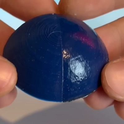
The smoothing process begins at the end of a 3D print and uses non-planar printer movements to keep the laser at an ideal focusing distance. The results proved rather effective, giving a noticeably smoother and shiner quality than an unprocessed print. The smoothing works incredibly well on fine geometry which would be difficult or impossible to smooth out via traditional mechanical means. Some detail was lost with sharp corners getting rounded, but not nearly as much as [TenTech] feared.

For a final test, [TenTech] made two candle molds, one smoothed and one processed. The quality difference between the two resulting candles was minimal, with the smoothed one being perhaps even a little worse. However, a large amount of wax leaked into the 3D print infill in the unprocessed mold, with the processed mold showing no signs of leaking.

If you are looking for a bit safer of a 3D print post-processing technique, make sure to check out [Donal Papp]’s UV resin smoothing experiments!

Continue reading “3D Print Smoothing, With Lasers”

A violet laser beam is shown expanding outward from a diode in a darkened room and illuminating the back of a man's hand.

Driving A Laser At 200 Volts For Nanoseconds

If there’s one lesson to be learned from [Aled Cuda]’s pulsed laser driver, it’s that you can treat the current limits on electronic components as a suggestion if the current duration is measured in nanoseconds.

The components in question are a laser diode and an NPN transistor, the latter of which operates in avalanche mode to drive nanosecond-range pulses of high current through the former. A buck-boost converter brings a 12 volt power supply up to 200 volts, which then passes through a diode and into the avalanche transistor, which is triggered by an external pulse generator. On the other side of the transistor is a pulse-shaping network of resistors and capacitors, the laser diode, and a parallel array of low-value resistors, which provide a current monitor by measuring the voltage across them. There is an optoisolator to protect the pulse generator from the 200 volt lines on the circuit board, but for simplicity’s sake it was omitted from this iteration; there is some slight irony in designing your own laser driver for the sake of the budget, then controlling it with “a pulse generator we don’t mind blowing up.” We can only assume that [Aled] was confident in his work.

The video below details the assembly of the circuit board, which features some interesting details, such as the use of a transparent solder mask which makes the circuit layout clear while still helping to align components during reflow. The circuit did eventually drive the diode without destroying anything, even though the pulses were probably 30 to 40 watts. A pulse frequency of 360 hertz gave a nice visual beating effect due to small mismatches between the pulse frequency of the driver and the frame rate of the camera.

This isn’t the first laser driver to use avalanche breakdown for short, high-power pulses, but it’s always good to see new implementations. If you’re interested in further high-speed electronics, we’ve covered them in more detail before.

Continue reading “Driving A Laser At 200 Volts For Nanoseconds”

A 3D-printed case encloses a number of electronic components. In the top left of the case, a laser diode is mounted. In the top right, the laser beam is shining into a cuvette, which is glowing red from scattered light. In the bottom right, a small breadboard has an integrated circuit and a few parts mounted. In the bottom left is a large red circuit board marked “Rich UNO R3.”

Measuring Nanoparticles By Scattering A Laser

A fundamental difficulty of working with nanoparticles is that your objects of study are too small for an optical microscope to resolve, and thus measuring their size can be quite a challenge. Of course, if you have a scanning electron microscope, measuring particle size is straightforward. But for less well-equipped labs, a dynamic light scattering system, such as [Etienne]’s OpenDLS, fits the bill.

Dynamic light scattering works by shining a laser beam into a suspension of fine particles, then using a light sensor to measure the intensity of light scattered onto a certain point. As the particles undergo Brownian motion, the intensity of the scattered light changes. Based on the speed with which the scattered light varies, it’s possible to calculate the speed of the moving particles, and thus their size.

The OpenDLS uses a 3D printed and laser-cut frame to hold a small laser diode, which shines into a cuvette, on the side of which is the light sensor. [Etienne] tried a few different options, including a photoresistor and a light sensor designed for Arduino, but eventually chose a photodiode with a two-stage transimpedance amplifier. An Arduino samples the data at 67 kHz, then sends it over serial to a host computer, which uses SciPy and NumPy to analyse the data. Unfortunately, we were about six years late in getting to this story, and the Python program is a bit out of date by now (it was written in Python 2). It shouldn’t, however, be too hard for a motivated hacker to update.

With a standard 188 nm polystyrene dispersion, the OpenDLS calculated a size of 167 nm. Such underestimation seemed to be a persistent issue, probably caused by light being scattered multiple times. More dilution of the suspension would help, but it would also make the signal harder to measure, and the system’s already running near the limits of the hardware.

This isn’t the only creative way to measure the size of small particles, nor even the only way to investigate small particles optically. Of course, if you do have an electron microscope, nanoparticles make a good test target.