Join us on Wednesday, October 13 at noon Pacific for the Resin Printing Hack Chat with Andrew Sink!
At its heart, 3D printing is such a simple idea that it’s a wonder nobody thought of it sooner. Granted, fused deposition modeling does go back to the 80s, and the relatively recent explosion in cheap, mass-market FDM printers has more to do with cheap components than anything else. But really, at the end of the day, commodity 3D printers are really not much more than glorified hot-glue guns, and while they’re still a foundational technology of the maker movement, they’ve gotten a bit dull.
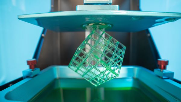
So it’s natural that we in this community would look for other ways to push the 3D printing envelope, and stereolithography has become the new hotness. And with good reason — messy though it may be, the ability to gradually pull a model from a tank of goo by selective photopolymerization looks magical, and the fine level of detail resin printers are capable of is just as enchanting. So too are the prices of resin printers, which are quickly becoming competitive with commodity FDM printers.
If there’s a resin printer in your future, then you’ll want to swing by the Hack Chat when Andrew Sink visits us. Andrew has been doing a lot of 3D printing stuff in general, and resin printing in particular, over on his YouTube channel lately. We’ve featured a couple of his tricks and hacks for getting the most from a resin printer, and he’ll be sharing some of what he has learned lately. Join us as we discuss the ins and outs of resin printing, what’s involved in taking the dive, and the pros and cons of SLA versus FDM.
 Our Hack Chats are live community events in the Hackaday.io Hack Chat group messaging. This week we’ll be sitting down on Wednesday, October 13 at 12:00 PM Pacific time. If time zones have you tied up, we have a handy time zone converter.