We’re blessed to have such a great community at Hackaday. Our tipline often overfloweth with all manner of projects and builds of all stripes. We see it all here, from beginners just starting out with their first Arduino to diehard hackers executing daringly complex builds in their downtime, and everything in between.
If you’re sitting there in the grandstands, watching in awe, you might wonder what it takes to grace these hallowed black pages. In life, nothing is guaranteed, but I’ve been specially authorised to share with you a few tips that can maximise your chances of seeing your project on Hackaday.
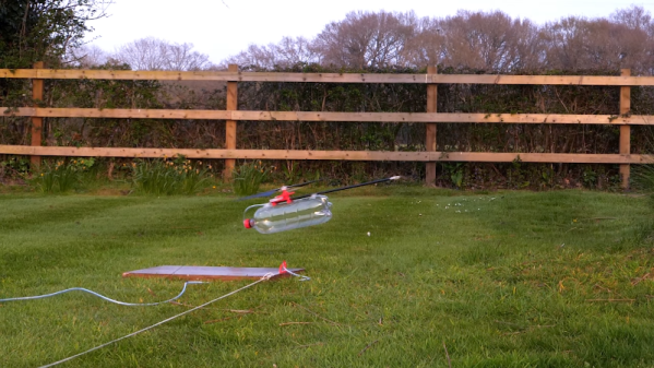
[Tom] likes to build little helicopters and decided to build one that runs on compressed air. (Video, embedded below.) Turns out it was a little harder than he thought. Originally, he was trying for a compressed air quadcopter. He’d already worked with an air turbine, but putting on a vehicle that can lift itself into the air turns out to have a lot of hidden gotchas.
[Tom] went through a lot of design considerations to arrive at the helicopter design. He considered counter-rotating props, but there were a host of problems involved. He finally settled on a single prob with a tail rotor that resides on the far end of a long boom to allow the resulting lever arm to reduce the work required of the tail rotor.
In the movies, everything is modular. Some big gun fell off the spaceship when it crashed? Good thing you can just pick it up and fire it as-is (looking at you, Guardians of the Galaxy 2). Hyperdrive dead? No problem, because in the Star Wars universe you can just drop a new one in and be on your way.
Of course, things just aren’t that simple in the real world. Most systems, be they spaceships or cell phones, are enormously complicated and contain hundreds or thousands of interconnected parts. If the camera in my Samsung phone breaks, I can’t exactly steal the one from my girlfriend’s iPhone. They’re simply not interchangeable because the systems were designed differently. Even if we had the same phone and the cameras were interchangeable, they wouldn’t be easy to swap. We’d have to crack open the phones and carefully perform the switch. Speaking of switches, the Nintendo Switch is a good counterexample here. Joycon break? Just buy a new one and pop it on.
What if more products were like the Nintendo Switch? Is its modularity just the tip of the iceberg?
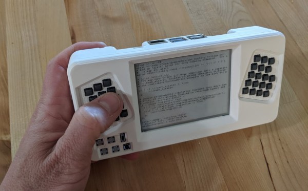
What’s the fastest way to master console stuff like screen or emacs? Force yourself to use it exclusively, of course. But maybe you’d be tempted to cheat with a desktop. We know we would be. In that case, you ought to build a console-only cyberdeck like this sweet little thing by [a8skh4].
This cyberdeck serves another purpose as well — the keyboard layout is Miryoku, so [a8ksh4] can get more practice with that at the same time. Fortunately, the layout is built for emacs.
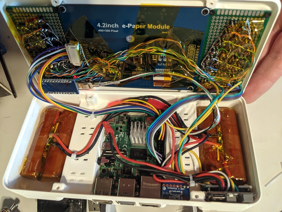
Inside is a Raspberry Pi 4 and what looks to be an Arduino handling the keyboard input. The Paper Pi spotlights a 4.2″ e-ink screen between a split thumb keyboard that’s made of soft, silent, tactile switches.
Since they’re SMD, [a8ksh4] made clever use of header pins to get them to work with protoboard. As much as we love the keyboard, it would be awesome to see a few switches on the shoulders or even the back that make use of the rest of the fingers. Check out more build pictures in the gallery.
Over the past few years a new class of soldering iron has arisen: a temperature controlled iron no longer tied to a bulky mains-powered base station, but using low-voltage DC power and with all electronics concealed in a svelte handle. First came the Miniware TS100, and then many more, with slightly different feature sets and at varying price points. We’ve reviewed a few of them over the years, and today we have the most recent contender in the Sequre SQ-D60. It follows the formula closely, but costs only £20 (about $26). This price puts it in an attractive budget category, and its USB-C power option makes it forward-looking over models with barrel jacks. Description over, it’s time to plug it in and put it through its paces.
What’s In The Box?
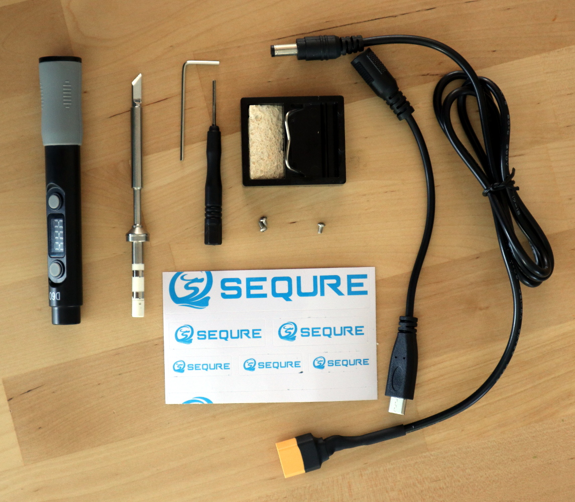
That’s a lot of extra bits for a budget iron!
In the box, aside from the handle containing the electronics, were a surprisingly comprehensive array of parts and accessories. The handle itself is similarly-sized to its competitors, being only slightly longer than that of Pine64’s Pinecil. The tip supplied was unexpectedly a slanted chisel, so I may have managed to order incorrectly, though since it shares the same tip design as both the TS100 and the Pinecil I have plenty of alternative tips should I need one. Otherwise there was a little bag of hex screws along with a key and a driver for them, a little stand with a sponge, a set of Sequre stickers, a USB-C to barrel jack cable, and a barrel jack-to-XT60 connector for use with LiPo battery packs. These last two cables are a particularly useful addition.
At first sight the tip doesn’t seem to have any means of being fixed into its socket, but a closer inspection reveals that there is a hex screw hiding underneath a silicone finger sleeve that holds it securely when tightened. The handle has a simple enough interface, with just two buttons and a 3-digit, 7-segment display. Powering it up from a 45 W USB-PD power supply, and it heats up to 300 °C in around ten seconds after pressing one of the buttons. My usual soldering temperature is 360 °C, and it has an interface involving long presses of one of the buttons before they become up and down buttons to select the temperature. In prolonged use the handle doesn’t become noticeably warm, and aside from a slight new-electronics-getting-hot smell there was no immediate concern that it might release magic smoke. Continue reading “Review: Sequre SQ-D60 Temperature Controlled Soldering Iron”→
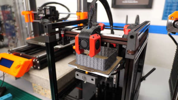
[Stefan] is always looking for a way to make stronger and better 3D prints. His latest experiments involve using a texture on thin plastic parts to increase stiffness. You can see the texture pattern in the banner above and the video below.
While a lot of people looked at IdeaMaker’s new texturing feature as something for cosmetics, [Stefan] thought of sheet metal products that often use bead patterns to increase stiffness and strength. Can patterned plastic be stiffer than ordinary printed plastic? Turns out, the answer is yes.
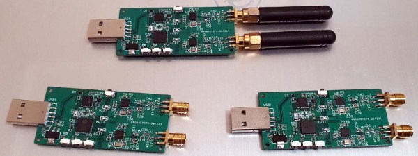
There’s no doubt that the RTL-SDR project has made radio hacking more accessible than ever, but there’s only so far you can go with a repurposed TV tuner. Obviously the biggest shortcoming is the fact that you can only listen to signals, and not transmit them. If you’re ready to reach out and touch someone, but don’t necessarily want to spend the money on something like the HackRF, the Evil Crow RF might be your ideal next step.
This Creative Commons licensed board combines two CC1101 radio transceivers and an ESP32 in one handy package. The radios give you access to frequencies between 300 and 928 MHz (with some gaps), and the fact that there are two of them means you can listen on one frequency while transmitting on another; opening up interesting possibilities for relaying signals. With the standard firmware you connect to a web interface running on the ESP32 to configure basic reception and transmission options, but there’s also a more advanced RFQuack firmware that allows you to control the hardware via Python running on the host computer.
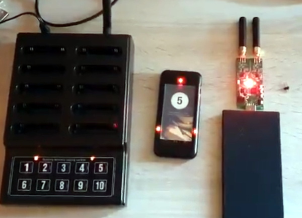
Using the Evil Crow RF without a computer.
One particularly nice feature is the series of buttons located down the side of the Evil Crow RF. Since the device is compatible with the Arduino IDE, you can easily modify the firmware to assign various functions or actions to the buttons.
In a demonstration by lead developer [Joel Serna], the physical buttons are used to trigger a replay attack while the device is plugged into a standard USB power bank. There’s a lot of potential there for covert operation, which makes sense, as the device was designed with pentesters in mind.