This time I promise I only have a couple of stories from Elon Musk’s company. SpaceX’s latest Starship test launch ended in another explosion, proving that space hardware remains hard to get right. We’ll keep watching as they keep launching, and it can’t be long until they’ve ironed out all the problems. Meanwhile there’s brighter news from the company’s Crew Dragon, a modified version of the capsule with the forward docking ring replaced by a transparent dome is planned for launch in September with the company’s first flight carrying civilian passengers. It’s doubtless unwelcome news for Virgin Galactic, whose suborbital passenger flights are edging closer to reality with the unveiling of their first SpaceShip III craft. Finally, a Falcon 9 upper stage broke up on re-entry over the northwestern USA, giving observers on the ground a spactacular show.

Meanwhile up there in orbit there have been found on the ISS some strains of bacteria previously unknown to scientists on Earth, but it’s not yet time to panic about Mutant Bugs From Space. It seems these bacteria are of a type that is essential in the growing of plants, so it’s likely they originally hitched a ride up with one of the several plant-growing experiments that have taken place over the station’s lifetime. Staying on the ISS, astronauts visiting the station have been at the centre of a recently published study looking at loss of bone density over long periods in space. The bone experts found that bone density could still be lost despite the astronauts’ in-flight exercise programs, and concluded that exercise regimes pre-flight should be taken into account for future in-orbit exercise planning.
Further away from Earth, the ESA Mars Express satellite has been used for a multi-year study of water loss to space from the Martian atmosphere. The ESA scientists identified the seasonal mechanism that leads to the planet’s upper atmosphere having an excess of water and in particular the effect of the periodic planet-wide dust storms on accelerating water loss, but failed to account for the water that they estimate Mars must have lost over its history. From a study of water-created surface features they can estimate how much liquid the planet once had, yet the atmospheric losses fail to account for it all. Has it disappeared underground? More studies are required before we’ll have an answer.
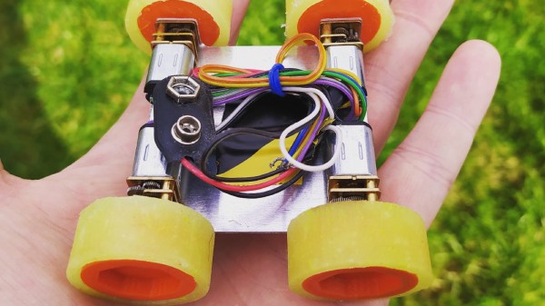
The exciting news over the coming days will no doubt be the Ingenuity Martian helicopter, which we have seen slowly unfolding itself prior to unloading from the belly of the Perseverence rover. If all goes according to plan the little craft will be set down before the rover trundles off to a safe distance, and the historic flight will take place on April 8th. We’ll be on the edges of our seats, and no doubt you will be, too.