Google has been responsible for unleashing some pretty incredible hardware and software on the world, but they can only take partial credit for the voice to Morse code gadget that [WhiskeyTangoHotel] recently completed.
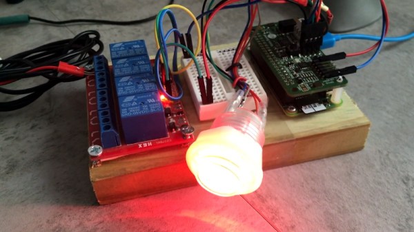
With the Google AIY Voice Bonnet, [WhiskeyTangoHotel] had everything he needed to pick up on human speech and turn that into text the Raspberry Pi can parse and act on. Usually this would get passed to some kind of virtual assistant software, but in this case, a Python script breaks the speech down into individual characters and looks up their Morse representations. All those “dits” and “dahs” are then sent to one of the Pi’s GPIO pins, to which a relay has been connected.
At this point, you’ve got an interesting little toy that can sit on your desk and turn your speech into audible Morse code as the relay clicks and clacks its way through the message. In fact, if you don’t have a ham radio license, this is probably where you should stop. But if you’ve done the appropriate paperwork to transmit over the air, the relay can be connected to a radio to actually transmit messages.
If you think giving Google access to the content of your Morse code messages is a step too far, you’ll just have to learn it yourself. It might not be necessary to get your amateur license anymore, but that doesn’t mean it’s not worth knowing.