Bench Power Supply Turned Realistic Flight Sim Panel

Flight simulator software has been available for about as long as desktop PCs have been a thing, but modern incarnations such as 2020’s Microsoft Flight Simulator have really raised the bar — not only graphically, but in terms of interactivity. There’s a dizzying array of switches and buttons that you can fiddle with in your aircraft’s virtual cockpit, but doing it with the same keyboard that you use to hammer out code or write Hackaday articles doesn’t do much for immersion.

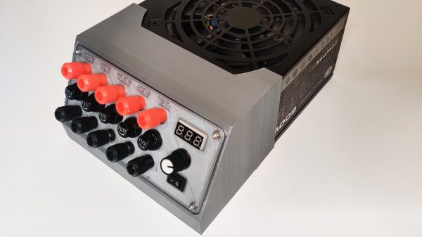
Looking to improve on the situation without having to shell out for an expensive sim panel, [Michael Fitzmayer] decided to convert a broken Manson SSP-8160 lab power supply into a fairly good approximation of the KAP 140 autopilot system which is used in one of his favorite aircraft, the Pilatus PC-6 Turbo-Porter.

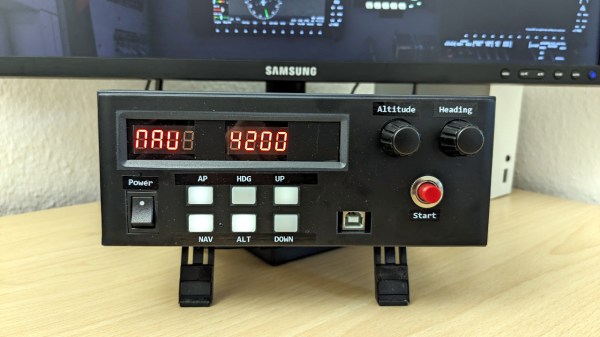
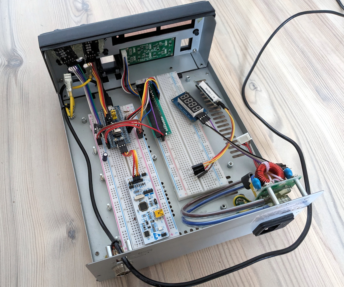
[Michael] gutted the piece of equipment pretty thoroughly, only leaving behind the case itself and the illuminated button panel on the front. The original displays were replaced with TM1637 seven-segment LEDs, and a pair of new rotary encoders are mounted where the stock knobs were. The whole show is run by a STM32F103 Blue Pill, which conveys the button pressing and knob spinning to the game by mimicking a USB Human Interface Device.

A fascia applied to the front of the power supply blocks the original text and labels, and really makes the finished unit look the part. [Michael] admits it’s not 100% accurate to the layout of the real hardware, but it’s certainly better than trying to enter heading and altitude information with the controller.

Oh that’s right, did we mention he’s actually using this on the Xbox Series S? While we generally see this sort of sim hardware hooked up to a tricked out gaming computer, we appreciate that he’s trying to bring some of that same experience to the console world. While the one-way communication of USB HID does bring with it some limitations — for example the hardware needs to be manually reset at the beginning of each flight to make sure the physical displays match what’s shown in the virtual cockpit– there’s still a lot of potential here.

For example, you could design and build your own flight yoke, pedals, and throttles rather than spending hundreds on a commercial version. It sounds like [Michael] is just getting started in the world of affordable console-based flight simulation, and we’re very eager to see where he goes from here.

Tearing Down And Improving A Professional Power Supply

[OZ2CPU] has an HP power supply that is about 30 years old. It looks brand new, though, and has three outputs and includes tracking for the adjustable positive and negative supply. After a quick demo of the unit’s features, he tears it all down so we can see inside. You can catch the video below.

Some similar supplies offer a 10-turn adjustment knob, but this one doesn’t. Inside is a beefy transformer and quite a few through-hole components. There was room to change the main adjusted pot to a 10-turn unit, so he made the mod.

Continue reading “Tearing Down And Improving A Professional Power Supply”

Spy Radio Setup Gets A Tiny Power Supply For Field Operations

[Helge Fyske (LA6NCA)] may not be an actual spy — then again, he may be; if he’s good at it, we wouldn’t know — but he has built a couple of neat vacuum tube spy radios in the past. And there’s no better test for such equipment than to haul it out into the field and try to make some contacts. But how do you power such things away from the bench?

To answer that question, skip ahead to the 3:18 mark of the video below, where [Helge] shows off his whole retro rig, including the compact 250-volt power supply he built for his two-tube 80-m Altoids tin spy transceiver. In the shack, [Helge] powers it with a bench power supply of his own design to provide the high anode voltage needed for the tubes, as well as 12 volts for their heaters. Portable operations require a more compact solution, preferably one that can be run off a battery small enough to pack in.

By building his power supply in a tin, [Helge] keeps to his compact build philosophy. But the circuit is all solid state, which is an interesting departure for him. The switch-mode supply uses a 4047 astable multivibrator chip as a 50-kHz oscillator, which switches back and forth between a pair of MOSFETs to drive a transformer. This steps up the 12-volt input to 280 volts AC, which is then rectified, filtered, and regulated to 250 volts DC.

To round out his spy rig, [Helge] also designed a tiny Morse key, which appears to be 3D printed and fits in its own tin, and a compact dipole antenna. Despite picking what appears to be a challenging location — the bottom of a steep-sided fjord — [Helge] was easily able to make contacts over a distance of 400 km. His noise floor was remarkably low, a testament to the solid design of his power supply. Including the sealed lead acid battery, the whole kit is compact and efficient, and it’s a nice example of what vacuum tubes and solid state can accomplish together.

Continue reading “Spy Radio Setup Gets A Tiny Power Supply For Field Operations”

Linear Power Supply’s Current Limiter Is A Lesson In Simplicity

Here at Hackaday we really like to feature projects that push the limits of what’s possible, or ones that feature some new and exciting technology that nobody has ever seen before. So what’s so exciting about this single-voltage linear power supply? Honestly, nothing — until you start looking at its thermally compensated current limiting circuit.

This one is by [DiodeGoneWild], who you’ve really got to hand it to in terms of both the empirical effort he went through to optimize the circuit, as well as the quality of his explanation. The basic circuit is dead simple: a transformer, a full-wave rectifier, an LD1085 adjustable regulator — a low-dropout version of the venerable LM317 — and associated filter caps and trimmer pot to adjust the output between 2.2 and 5.5 volts.

The current limiting circuit, though, is where things get interesting. Rather than use an op-amp, [DiodeGoneWild] chose a simple discrete transistor current-sense circuit. To make it less susceptible to thermal drift, he experimented with multiple configurations of resistors and Schottky diodes over a wide range of temperatures, from deep-freeze cold to hair-dryer-in-a-box hot. His data table and the resulting graph of current versus temperature are works of art, and they allowed him to make sensible component selections for a fixed 250-mA current limit with a reasonably flat thermal response.

As for construction, it’s all classic [DiodeGoneWild], including a PCB with traces ground out with a Dremel and a recycled heat sink. He also dropped a couple of interesting build techniques, like adding leads to turn SMD tantalum caps into through-hole components. The video below shows all the build details along with the exhaustive breadboard testing.

From taking on a potentially risky magnetron teardown to harvesting lasers from headlights, there’s always something to learn from a [DiodeGoneWild] video.

Continue reading “Linear Power Supply’s Current Limiter Is A Lesson In Simplicity”

High Voltage Power Supply From USB

Those who work in different spaces may have different definitions of the term “high voltage”. For someone working on the GPIO pins of a Raspberry Pi it might be as little as 5 volts, someone working on a Tesla coil might consider that to be around 20 kV, and an electrical line worker might not reference something as HV until 115 kV. What we could perhaps all agree on, though, is that getting 300 volts out of a USB power supply is certainly a “high voltage” we wouldn’t normally expect to see in that kind of context, but [Aylo6061] needed just such a power supply and was eventually able to create one.

In this case, the high voltages will eventually be used for electrophoresis or electrowetting. But before getting there, [Aylo6061] has built one of the safest looking circuits we’ve seen in recent memory. Every high voltage part is hidden behind double insulation, and there is complete isolation between the high and low voltage sides thanks to a flyback converter. This has the benefit of a floating ground which reduces the risk of accidental shock. This does cause some challenges though, as voltage sensing on the high side is difficult while maintaining isolation, so some clever tricks were implemented to maintain the correct target output voltage.

The control circuitry is based around an RP2040 chip and is impressive in its own right, with USB isolation for the data lines as well. Additionally the project code can be found at its GitHub page. Thanks to a part shortage, [Aylo6061] dedicated an entire core of the microprocessor to decoding digital data from the high voltage sensor circuitry. For something with a little less refinement, less safety, and a much higher voltage output, though, take a look at this power supply which tops its output voltage around 30 kV.

Ask Hackaday: Split Rail Op Amp Power Supply

Water cooler talk at the office usually centers around movies, sports, or life events. Not at Hackaday. We have the oddest conversations and, this week, we are asking for your help. It is no secret that we have a special badge each year for Supercon. Have you ever wondered where those badges come from? Sometimes we do too. We can’t tell you what the badge is going to be for Supercon 2023, but here’s a chance for you to contribute to its design.

What I can tell you is that at least part of the badge is analog. Part, too, is digital. So we were discussing a seemingly simple question: How do we best generate a bipolar power source for the op amps on a badge? Like all design requests, this one is unreasonable. We want:

  • Ideally, we’d like a circuit to give us +/- 9 V to +/- 12 V at moderately low current, say in the tens of milliamps. Actual values TBD.
  • Low noise: analog circuitry, remember?
  • Lightweight: it is going on a badge
  • Battery operated: the badge thing again
  • Cheap: we only have a couple bucks in the budget for power
  • Available in quantity: we’ll need ~600 of these

Continue reading “Ask Hackaday: Split Rail Op Amp Power Supply”

Simple ATX Bench Power Supply Adds Variable Output

A benchtop power supply is a key thing to have for any aspiring electronics hacker. While you can always buy one, plenty of us have old computer PSUs lying around that could do a fine job themselves. [Frugha] decided to whip up a neat 3D-printed design for converting any ATX PSU into a usable bench unit.

The design features banana plugs outputting +12V, -12V, +5V, and +3.3V, with all outputs appropriately fused for safety. There’s also a fused stepdown converter used to supply variable voltages as needed. Its original trimpot was replaced with a multi-turn pot for ease of control. To make everything work, a load resistor on the 5V circuit makes the power supply think it’s hooked up to a motherboard. It’s all wrapped up in a neat slant-sided 3D-printed case that fits onto the ATX power supply itself.

The result is a neat and tidy power supply built out of readily-available components. We particularly like the addition of the stepdown converter – most ATX-based projects don’t offer variable output, which can nonetheless come in handy.

We’ve seen some other great builds along these lines before, too. If you’ve been cooking up your own homebrew power supply, don’t hesitate to share it on the tipsline!