Knockoff Kapton Nearly Sinks DIY Flex PCB Project

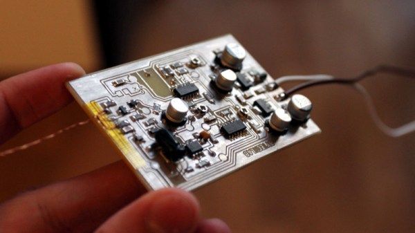
[TinkersProjects] experimented with making their own flexible PCB for LED modules inside a special fixture, and the end result was at least serviceable despite some problems. It does seem as though the issues can be at least partially blamed on some knockoff Kapton tape, which is what [TinkersProjects] used as a backing material.

Incomplete etching on this DIY flexible PCB, but still salvageable.

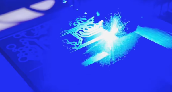
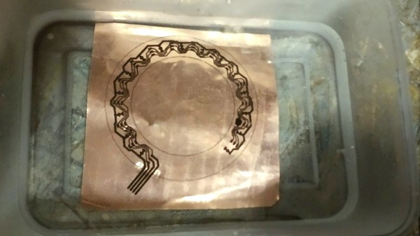
The approach was simple: after buying some copper foil and wide Kapton tape, simply stick the foil onto the tape and use the toner transfer method to get a PCB pattern onto the copper. From there, the copper gets etched away in a chemical bath and the process is pretty much like any other DIY PCB. However, this is also where things started to go wonky.

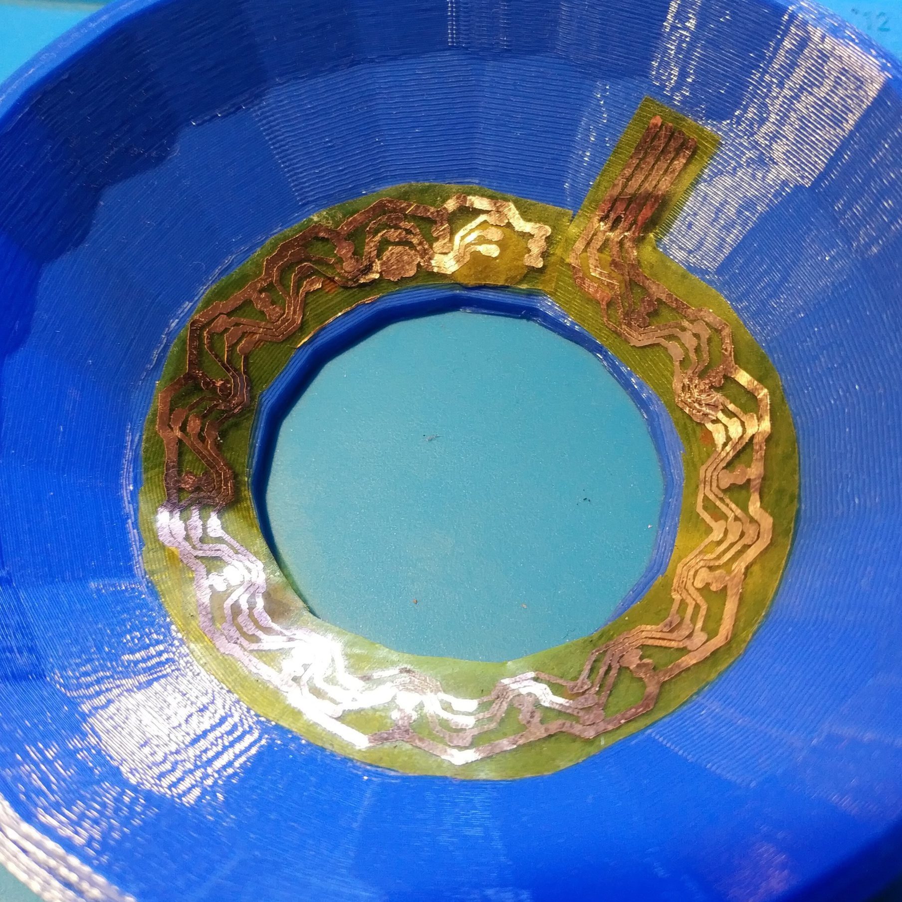
Etching was going well, until [TinkersProjects] noticed that the copper was lifting away from the Kapton tape. Aborting the etching process left a messy board, but it was salvageable. But another problem was discovered during soldering, as the Kapton tape layer deformed from the heat, as if it were a piece of heat shrink. This really shouldn’t happen, and [TinkersProjects] began to suspect that the “Kapton” tape was a knockoff. Switching to known-good tape was an improvement, but the adhesive left a bit to be desired because traces could lift easily. Still, in the end the DIY flexible PCB worked, though the process had mixed results at best.

Flexible PCBs have been the backbone of nifty projects like this self-actuating PoV display, so it’s no surprise that a variety of DIY PCB methods are getting applied to it.

Hackaday Podcast 089: 770 Potato Battery, Printing Resin Resist, And No-Internet Video Chat

Hackaday editors Mike Szczys and Elliot Williams weigh the hacking gold found across the internet this week. We can’t get over the epic adventure that went into making a battery from 100 pounds of potatoes. It turns out you don’t need Internet for video conferencing as long as you’re within a coupe of kilometers of everyone else. And move over toner transfer method, resin printers want a shot at at-home PCB etching. We’ll take a look at what the Tesla selfie cam is doing under the hood, and lose our marbles over a ball-bearing segment clock that’s defying gravity.

Take a look at the links below if you want to follow along, and as always, tell us what you think about this episode in the comments!

Take a look at the links below if you want to follow along, and as always, tell us what you think about this episode in the comments!

Direct download (60 MB or so.)

Continue reading “Hackaday Podcast 089: 770 Potato Battery, Printing Resin Resist, And No-Internet Video Chat”

Another Way To Make PCBs At Home

One of the more popular ways of rolling out your own custom PCB is to simply create the model in your CAD program of choice and send it off to a board manufacturer who will take care of the dirty work for you. This way there is no need to deal with things like chemicals, copper dust, or maintaining expensive tools. A middle ground between the board manufacturer and a home etching system though might be what [igorfonseca83] has been doing: using an inexpensive laser engraver to make PCBs for him.

A laser engraver is basically a low-power laser CNC machine that’s just slightly too weak to cut most things that would typically go in a laser cutter. It turns out that the 10W system is the perfect amount of energy to remove a mask from a standard PCB blank, though. This in effect takes the place of the printer in the old toner transfer method, and the copper still has to be dissolved in a chemical solution, but the results are a lot more robust than trying to modify a printer for this task.

If you aren’t familiar with the days of yore when homebrew PCBs involved a standard desktop printer, many people still use this method, although the results can be mixed based on printer reliability. If you want to skip the middleman, and the need for a chemical bath, a more powerful laser actually can cut the traces for you, too.

Continue reading “Another Way To Make PCBs At Home”

Etching Large Brass Sheets Is Harder Than You Think

One of my favorite ways to think of engineering is that a glass is not half empty or half full, only twice as large as it needs to be. As useful as that idea is, it also means that I rarely put any effort into the aesthetics of my projects – I learn or accomplish what I need, desolder and recycle the components, then move on. Few of my projects are permanent, and custom cases tend to be non-reusable, so I skip the effort and expense.

Once in a while though, I need to make a gift. In that case form and function both become priorities. Thankfully, all that glitters is not gold – and over the last year I’ve been learning to etch the copper alloys commonly classified as ‘brass’. We’ve covered some truly excellent etched brass pieces previously, and I was inspired to try and etch larger pieces of metal (A4 and larger) without sacrificing resolution. I thought this would be just like etching circuits. In fact, I went through several months of failed attempts before I produced anything halfway decent!

Although I’m still working on perfecting my techniques, I’ve learned enough in the meantime to give a report. Read on if you’re feeling the need for more fancy brass signs in your life.

Continue reading “Etching Large Brass Sheets Is Harder Than You Think”

Component Shelf Life: How To Use All That Old Junk

There are two types of Hackaday readers: those that have a huge stock of parts they’ve collected over the years (in other words, an enormous pile of junk) and those that will have one a couple of decades from now. It’s easy to end up with a lot of stuff, especially items that you’re likely to use in more than one design; the price breakpoints at quantities of 10 or 100 of something can be pretty tempting, and having a personal stock definitely speeds the hacking process now that local parts shops have gone the way of the dinosaur. This isn’t a perfect solution, though, because some components do have shelf-lives, and will degrade in some way or another over time.

If your stash includes older electronic components, you may find that they haven’t aged well, but sometimes this can be fixed. Let’s have a look at shelf life of common parts, how it can be extended, and what you can do if they need a bit of rejuvenation.

Continue reading “Component Shelf Life: How To Use All That Old Junk”

The Embroidered Computer

By now we’ve all seen ways to manufacture your own PCBs. There are board shops who will do small orders for one-off projects, or you can try something like the toner transfer method if you want to get really adventurous. One thing we haven’t seen is a circuit board that’s stitched together, but that’s exactly what a group of people at a Vienna arts exhibition have done.

The circuit is stitched together on a sheet of fabric using traditional gold embroidery methods for the threads, which function as the circuit’s wires. The relays are made out of magnetic beads, and the entire circuit functions as a fully programmable, although relatively rudimentary, computer. Logic operations are possible, and a functional schematic of the circuit is also provided. Visitors to the expo can program the circuit and see it in operation in real-time.

While this circuit gives new meaning to the term “wearables”, it wasn’t intended to be worn although we can’t see why something like this couldn’t be made into a functional piece of clothing. The main goal was to explore some historic techniques of this type of embroidery, and explore the relationship we have with the technology that’s all around us. To that end, there have been plenty of other pieces of functional technology used as art recently as well, but of course this isn’t the first textile computing element to grace these pages.

Thanks to [Thinkerer] for the tip!


LED “Candle” Gets The 555 Treatment

Regular readers may recall we recently covered a neat Arduino trick that allowed you to “blow out” an LED as if it was a candle. The idea was that the LED itself could be used as a rudimentary temperature sensor, and the Arduino code would turn the LED on and off when a change was detected in its forward voltage drop. You need to oversample the Arduino’s ADC to detect the few millivolt change reliably, but overall it’s pretty simple once you understand the principle.

But [Andrzej Laczewski], like many of our beloved readers, feels the Arduino and other microcontrollers can be a crutch if used exclusively. So he set out to replicate this hack with that most cherished of ICs, the 555 timer. In the video after the break, he demonstrates his “old-school” LED candle for anyone who thinks the only way to control an LED is with digitalWrite.

Not to say it’s easy to replicate the original Arduino project with a 555, or that it’s even practical. [Andrzej] simply wanted to show it was possible, which is something we always respect around these parts. He goes into great detail on how he developed and tested the circuit, even including oscilloscope screenshots showing how the different components work together in real-time. But the short version is that a MOSFET is used to turn the LED on and off, a comparator detects change in the LED’s voltage drop, and the 555 is used to control how long the LED stays off for.

Ever the traditionalist, [Andrzej] wrapped up this build by etching his own PCB using a variation of the classic laser toner transfer method. If this all looks a bit too much like Black Magic to you, there’s no shame in sticking with the Arduino version. At 1/20th of the parts count, and with no calibration required, who’s to say which version is “simpler”.

Continue reading “LED “Candle” Gets The 555 Treatment”