Making An Arduino Shield PCB With Fritzing

[Allan Schwartz] decided to document his experience using Fritzing to design, fabricate, and test a custom Arduino shield PCB, and his step-by-step documentation makes the workflow very clear. Anyone who is curious or has been looking for an opportunity to get started will find [Allan]’s process useful to follow. The PCB in question has two shift registers, eight LEDs, eight buttons, and fits onto an Arduino; it’s just complex enough to demonstrate useful design features and methods while remaining accessible.

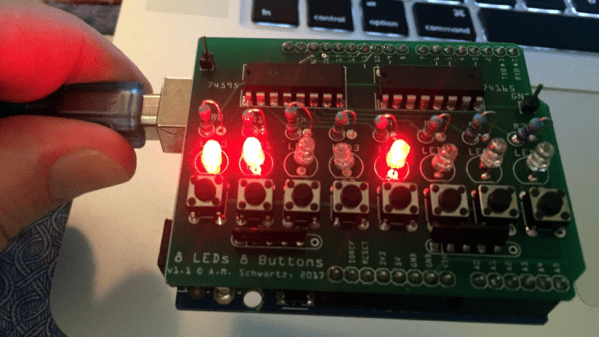
[Allan] starts with a basic breadboard design, draws a schematic, prototypes the circuit, then designs the PCB and orders it online, followed by assembly and testing. [Allan] had previously taught himself to use Eagle and etched his own PCBs via the toner transfer method, but decided to use Fritzing instead this time around and found it helpful and easy to use.

About a year ago we saw Fritzing put through its paces for PCB design, and at the time found that it didn’t impress much from an engineering perspective. Regardless, as a hobbyist [Allan] found real value in using Fritzing for his project from beginning to end; he documented both the process and his observations in order to help others, and that’s wonderful.

Wearable Foxhunt Transmitter For Conventions

Amateur radio operator [KE4FOX] wanted to build his own 2M fox hunt transmitter for use at conventions. It would be contained in a 1020 Pelican micro case and attached to a person who would walk around transmitting a signal, leaving the hams to track down the fox. The project uses a DRA818 VHF/UHF transceiver plugged into a low-pass filter combined with a hardware DTMF decoder, all controlled by an ATmega328P and powered by a 11.2 mAh battery.

[KE4FOX] also etched his own PCB, using the PCB toner transfer method, folding a sheet of transfer paper around the board to align both layers. Then he etched the board using cupric chloride. When assembling the board he realized he had made a terrible error, assuming the transceiver module’s pins went in the top layer when in fact they should have gone in the bottom layer. He solved this by soldering in the module in upside down.

He dropped the project into the 1020 and installed an SMA antenna. After he assembled the project he found out that the level shifter he used on the Arduino’s 5 V data didn’t work as expected and it was stuck at a single frequency. Something to work on for V2!

We publish a large number of amateur radio posts here on Hackaday, including fox hunting with Raspberry Pi and how to make a TDOA directional antenna.

[thanks, that Kat!]

Hackaday Prize Entry: PCBs On Demand With Etchr

The ambitious etchr – the PCB Printer is just a concept at the moment, but it’s not often we see someone trying to tackle desktop PCB production in a new way. Creator [Jonathan Beri] is keenly aware that when it comes to creating electronics, the bottleneck for most workflows is the PCB itself. Services like OSH Park make professionally fabricated PCBs accessible at a low cost, but part of the bargain is that turnaround times are often measured in weeks.

[Jonathan]’s concept for etchr is a small system that automates not only etching a copper-clad board with all the attendant flooding and draining of chemicals, but applying a solder mask and silkscreen layer labeling as well. The only thing left to do would be to drill any required holes.

The idea behind etchr is to first take a copper-clad board with photoresistive film or spray applied to it, and fix it into a frame. A UV projector takes care of putting the traces pattern onto the board (and also handles a UV-curable solder mask in a later step) and the deep frame doubles as a receptacle for any chemical treatments such as the etching and cleaning. It’s an ambitious project, but the processes behind each step are well-understood and bringing them all together in a single machine is an intriguing approach.

Desktop production of PCBs can be done in a few ways, including etching via the toner transfer method (whose results our own Elliot Williams clearly explained how to take from good to great). An alternative is to mill the PCBs out directly, a job a tool like the Othermill is designed specifically to do. It’s interesting to see an approach that includes applying a solder mask.

From Zero To Nano

Have you ever wanted to build your own Arduino from scratch? [Pratik Makwana] shares the entire process of designing, building and flashing an Arduino Nano clone. This is not an entry-level project and requires some knowledge of soldering to succeed with such small components, but it is highly rewarding to make. Although it’s a cheap build, it’s probably cheaper to just buy a Nano. That’s not the point.

The goal here and the interesting part of the project is that you can follow the entire process of making the board. You can use the knowledge to design your own board, your own variant or even a completely different project.

from-zero-to-nano-thumb
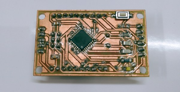
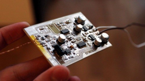
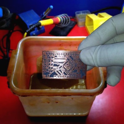
[Pratik Makwana] starts by showing how to design the circuit schematic diagram in an EDA tool (Eagle) and the corresponding PCB layout design. He then uses the toner transfer method and a laminator to imprint the circuit into the copper board for later etching and drilling. The challenging soldering process is not detailed, if you need some help soldering SMD sized components we covered some different processes before, from a toaster oven to a drag soldering process with Kapton tape.

Last but not least, the bootloader firmware. This was done using an Arduino UNO working as master and the newly created the Arduino Nano clone as target. After that you’re set to go. To run an actual sketch, just use your standard USB to UART converter to burn it and proceed as usual.

Voilá, from zero to Nano:

Continue reading “From Zero To Nano”

Want To Make A PCB? The Pantum Knows…

We’ve done a lot of PCBs with the toner transfer method over the years. The idea is simple: print a pattern using toner (which is just ground up black plastic) and then use an iron or other heat and pressure device to transfer the toner to a copper-clad board. It works and it works well. But getting just the right combination of heat, pressure, release paper, and toner is sometimes tricky.

Some people hack their printers to turn off the fuser wire (to make the toner not stick to the paper) or to run a PCB directly through it. If you have a big expensive laser printer, though, you might not want to chop it up just to run PCBs. Have you looked at laser printer prices lately? We aren’t sure if it is cheap units flooding the market, or the overwhelming popularity of color printers, but you can pick up a Pantum P2500 for about $25 or $30–and probably get WiFi printing at that price. [Mlermen] picked one of these up and shows you how to convert it to a PCB printer.

Continue reading “Want To Make A PCB? The Pantum Knows…”

DIY Smartwatch Based On ESP8266 Needs Classification

Building your own smartwatch is a fun challenge for the DIY hobbyist. You need to downsize your electronics, work with SMD components, etch your own PCBs and eventually squeeze it all into a cool enclosure. [Igor] has built his own ESP8266-based smartwatch, and even though he calls it a wrist display – we think the result totally sells as a smartwatch.

His design is based on a PCB for a wireless display notifier he designed earlier this year. The design uses the ESP-12E module and features an OLED display, LEDs, tactile switches and an FT232R USB/UART interface. Our beloved TP4056 charging regulator takes care of the Lithium-ion cell and a voltage divider lets the ESP8266’s ADC read back the battery voltage. [Igor] makes his own PCBs using the toner transfer method, and he’s getting impressive results from his hacked laminator.

Together with a hand-made plastic front, everything fits perfectly into the rubber enclosure from a Jelly Watch. A few bits of Lua later, the watch happily connects to a WiFi network and displays its IP configuration. Why wouldn’t this be a watch? Well, it lacks the mandatory RTC, although that’s easy to make up for by polling an NTP time server once in a while. How would our readers classify this well-done DIY build? Let us know in the comments!

New Hard Drives For Old Computers

After a certain age, computers start to show signs that they might need to be replaced or upgraded. After even more time, it starts getting hard to find parts to replace the failing components. And, as the sands slip through the hourglass, the standards used to design and build the computer start going obsolete. That’s the situation that [Drygol] found himself in when he was asked to build a SD-card hard drive for an Atari.

The 8-bit Atari in question was a fixture of home computing in the 80s. In fact, if you weren’t on the Commodore train, it’s likely that your computer of choice was an Atari. For the nostalgic among us, a new hard drive for these pieces of history is a great way to relive some of the past. Working off of information from the SIO2SD Wiki page, [Drygol] used the toner transfer method to build a PCB, 3D printed a case, and got to work on his decades-old computer.

Resurrecting old hardware is a great way to get into retrocomputing. Old protocols and standards are worth investigating because they’re from a time where programmers had to make every bit count, and there are some gems of genius hidden everywhere. Whether you’re reworking SIO from an old Atari, or building a disk emulator for an Apple ][, there are lots of options.