Printing Antennas On Circuit Boards

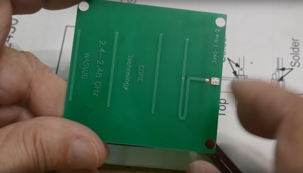
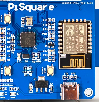
Yagi-Uda antennas, or simply “Yagis”, are directional antennas that focus radio waves to increase gain, meaning that the radio waves can travel further in that direction for a given transmitter power. Anyone might recognize an old TV antenna on a roof that uses this type of antenna, but they can be used to increase the gain of an antenna at any frequency. This one is designed to operate within the frequencies allotted to WiFi and as a result is so small that the entire antenna can be printed directly on a PCB.

The antenna consists of what is effectively a dipole antenna, sandwiched in between a reflector and three directors. The reflector and directors are passive elements in that they interact with the radio wave to focus it in a specific direction, but the only thing actually powered is the dipole in the middle. It looks almost like a short circuit at first but thanks to the high frequencies involved in this band, will still function like any other dipole antenna would. [IMSAI Guy], who created the video linked above which goes over these details also analyzed the performance of this antenna and found it to be fairly impressive as a WiFi antenna, but he did make a few changes to the board for some other minor improvements in performance.

The creator of these antennas, [WA5VJB] aka [Kent Britain] is an antenna builder based in Texas who has developed a few unique styles of antennas produced in non-traditional ways. Besides this small Yagi, there are other microwave antennas available for direction-finding, some wide-band antennas, and log-periodic antennas that look similar to Yagi antennas but are fundamentally different designs. But if you’re looking to simply extend your home’s WiFi range you might not need any of these, as Yagi antennas for home routers can be a lot simpler than you ever imagined.

Continue reading “Printing Antennas On Circuit Boards”

PCB antenna rendered useless by overly enthusiastic copper fill.

The Many Ways You Can Easily Ruin Your PCB Antenna Design

PCB antenna impaired by copper fill and other attenuation sources.

We have all seen Printed Circuit Board (PCB) antennas: those squiggly bits of traces on PCBs connected often to a Bluetooth, WiFi or other wireless communication chip. On modules like for the ESP8266 and ESP32 platforms the PCB antennas are often integrated onto the module’s PCB, yet even with such a ready-made module it’s possible to completely destroy the effectiveness of this antenna. These and other design issues are discussed in this article by [MisterHW].

It covers a range of examples of poor design, from having ground fill underneath an antenna, to having metal near the antenna, to putting dielectric materials near or on top of the antenna. The effect of all of these issues is generally to attenuate the signal, sometimes to the point where the antenna is essentially useless.

Ultimately, the best PCB antenna design is one where there is no nearby copper fill, and there are no traces running near or on layers below the antenna. After all, any metal trace or component is an antenna, and any dielectric materials will dampen the signal. Fortunately, there is e.g. a free KiCad library with ready-to-use PCB antenna designs to help one get started with a custom design, as well as many other resources, covered in the article.

If you want to get really professional about checking the effectiveness of an antenna design, you’ll want to use a Network Vector Analyzer. These will also help you with tuning the capacitors used with the PCB antenna.

(Featured image: PCB antenna rendered useless by overly enthusiastic copper fill.)

DIY Video Transmitter Turned WiFi Jammer

The proliferation of FPV drones has brought a flood of cheap wireless video tech. After flying and crashing a cheap FPV drone for a bit, [GreatScott] decided to try his hand at building his own video transmitter, which turned out to be a lot harder than expected.

While digital technology has caught up to the FPV world, a lot of systems still use analog video, especially for drone racing. The video quality isn’t great, but it has the advantage of very low latency. The technology is very similar to the old analog TV broadcasts, but mainly uses the 5.8 GHz license-free bands. It is essentially analog video signal, frequency modulated onto a 5.8 GHz carrier signal transmitted through an appropriately sized antenna.

After a brief failed experiment with a simple circuit built from discrete components, [GreatScott] turned his attention to voltage-controlled oscillators (VCO). He bought a couple of 5.8 GHz VCOs from Aliexpress, and created and used a simple opamp circuit to boost the FPV camera video signal to the required input level for the VCO. This failed to produce any identifiable image on his video receiver goggles. In an attempt to confirm that the VCOs produced the desired frequency, he ordered a similar 2.4 GHz VCOs and built a short range (20 cm) WiFi jammer. With a signal generator to create a simple input signal, and confirmed that it interfered with his laptop’s WiFi connection.

After more experimentation with other VCOs, the closest [GreatScott] came to success was a barely identifiable image transmitted using a Maxim 2.4 GHz VCO. If you have any ideas on what is missing in the VTX circuit, drop them in the comments below.

Building RF circuits that interfere with the legitimate signal around you, or broadcasting out of band, is generally not a great idea, and could earn you an unpleasant visit from the authorities. If you want to build your own digital video transmission, take a look at the Wifibroadcast project.

Continue reading “DIY Video Transmitter Turned WiFi Jammer”

SATAn Turns Hard Drive Cable Into Antenna To Defeat Air-Gapped Security

It seems like [Mordechai Guri]’s lab at Ben-Gurion University is the place where air-gapped computers go to die, or at least to give up their secrets. And this hack using a computer’s SATA cable as an antenna to exfiltrate data is another example of just how many side-channel attacks the typical PC makes available.

The exploit, deliciously designated “SATAn,” relies on the fact that the SATA 3.0 interface used in many computers has a bandwidth of 6.0 Gb/s, meaning that manipulating the computer’s IO would make it possible to transmit data from an air-gapped machine at around 6 GHz. It’s a complicated exploit, of course, and involves placing a transmitting program on the target machine using the usual methods, such as phishing or zero-day exploits. Once in place, the transmitting program uses a combination of read and write operations on the SATA disk to generate RF signals that encode the data to be exfiltrated, with the data lines inside the SATA cable acting as antennae.

SATAn is shown in action in the video below. It takes a while to transmit just a few bytes of data, and the range is less than a meter, but that could be enough for the exploit to succeed. The test setup uses an SDR — specifically, an ADALM PLUTO — and a laptop, but you can easily imagine a much smaller package being built for a stealthy walk-by style attack. [Mordechai] also offers a potential countermeasure for SATAn, which basically thrashes the hard drive to generate RF noise to mask any generated signals.

While probably limited in its practical applications, SATAn is an interesting side-channel attack to add to [Dr. Guri]’s list of exploits. From optical exfiltration using security cameras to turning power supplies into speakers, the vulnerabilities just keep piling up.

Continue reading “SATAn Turns Hard Drive Cable Into Antenna To Defeat Air-Gapped Security”

Sketch of the two proprietary carriers showing their differences - one of them has a cutout under the antenna, while the other one does not.

Design Your CM4 Carrier With WiFi Performance In Mind

The Raspberry Pi Compute Module 4 has a built-in WiFi antenna, but that doesn’t mean it will work well for you – the physical properties of the carrier board impact your signal quality, too. [Avian] decided to do a straightforward test – measuring WiFi RSSI changes and throughput with a few different carrier boards. It appears that the carriers he used were proprietary, but [Avian] provides sketches of how the CM4 is positioned on these.

There’s two recommendations for making WiFi work well on the CM4 – placing the module’s WiFi antenna at your carrier PCB’s edge, and adding a ground cutout of a specified size under the antenna. [Avian] made tests with three configurations in total – the CMIO4 official carrier board which adheres to both of these rules, carrier board A which adheres to neither, and carrier board B which seems to be a copy of board A with a ground cutout added.

Graph plotting WiFi RSSI for each of the three carriers in each of the six locations. CMIO4 consistently outperforms both, while carrier B outperforms the carrier A, but by a more narrow margin.
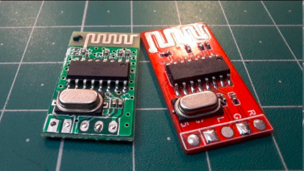
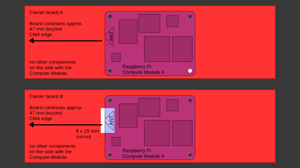
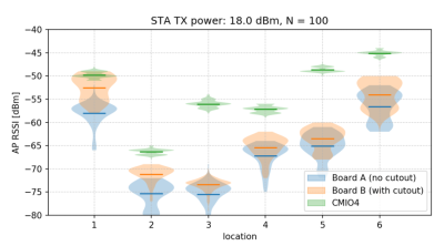
After setting up some test locations and writing a few scripts for ease of testing, [Avian] recorded the experiment data. Having that data plotted, it would seem that, while presence of an under-antenna cutout helps, it doesn’t affect RSSI as much as the module placement does. Of course, there’s way more variables that could affect RSSI results for your own designs – thankfully, the scripts used for logging are available, so you can test your own setups if need be.

If you’re lucky to be able to design with a CM4 in mind and an external antenna isn’t an option for you, this might help in squeezing out a bit more out of your WiFi antenna. [Avian]’s been testing things like these every now and then – a month ago, his ESP8266 GPIO 5V compatibility research led to us having a heated discussion on the topic yet again. It makes sense to stick to the design guidelines if WiFi’s critical for you – after all, even the HDMI interface on Raspberry Pi can make its own WiFi radio malfunction.

A modified Ghostbusters Proton Pack

Track Down Ghosts In Your WiFi With The Pwnton Pack

If there’s something weird in your Network Neighborhood, who you gonna call? If you want your WiFi troubles diagnosed in style, try calling [Travis Kaun] — he might just show up wearing the amazing Pwnton Pack. Built from a replica Proton Pack similar to those used in the 1984 classic Ghostbusters, it’s a portable wireless security diagnostics kit that should be able to pinpoint any weaknesses in your wireless network.

Inside, it’s got a Mark VII WiFi Pineapple, which is a portable device designed for security testing purposes, as well as a Raspberry Pi running Pwnagotchi: a deep learning-based WiFi sniffer that aims to capture those network packets that help maximize your chances of brute-forcing the WPA key. These two devices are connected to an array of antennas, including a cool rotating 5 GHz panel antenna to scan the surrounding area.

Naturally, the Pwnton Pack also includes a Neutrona Wand, which in this case contains a 2.4 GHz Yagi antenna hooked up to an ESP32 programmed to perform deauthentication attacks. An Arduino Nano drives an LED matrix that shows scrolling Pac-Man ghosts, while a dedicated sound board provides movie sound effects. The whole system is powered by three LiPo battery packs, and can even be remotely operated if desired.

Sadly, it doesn’t come with one of those ghost traps to suck up wayward WiFi networks, but the range of tools available should help to catch any kind of weird phantoms hiding in your system. We’ve spotted a few Proton Packs before, but never one with such advanced functionality. Security testing systems tend to be a bit less conspicuous, after all. Continue reading “Track Down Ghosts In Your WiFi With The Pwnton Pack”

New Pi Zero Gains Unapproved Antennas Yet Again

We’ve only started to tap into the potential of the brand new Pi Zero 2. Having finally received his board, [Brian Dorey] shows us how to boost your Pi’s WiFi, the hacker way. Inline with the onboard WiFi antenna can be found a u.FL footprint, and you just know that someone had to add an external antenna. This is where [Brian] comes in, with a photo-rich writeup and video tutorial, embedded below, that will have you modify your own Zero in no time. His measurements show seeing fourteen networks available in a spot where he’d only see four before, and the RSSI levels reported have improved by 5 dB -10 dB, big when it comes to getting a further or more stable connection.

With old laptops being a decent source of WiFi antennas, you only need to procure a u.FL connector and practice soldering a bit before you take this on! The hardest part of such a project tends to be not accidentally putting any solder on the u.FL connector’s metal can – and [Brian] mostly succeeds in that! He shows how to disconnect the external antenna to avoid signal reflections and the like, and, of course, you will be expected to never power your Pi Zero on without an attached antenna afterwards, lest you have your transmitter become fatally confused by the mismatch of hardware-defined impedance expectations. A Pi Zero isn’t the only place where you’ll encounter footprints for connectors you can add, and arguably, that’s your duty as a hacker – modifying the things you work with in a way that adds functionality. Don’t forget to share how you did it!

This trick should be pretty helpful if you’re ever to put your new Pi Zero in a full-metal enclosure. Curious about the Raspberry Pi antenna’s inner workings? We’ve covered them before! If you’d like to see some previous Raspberry Pi mods, here’s one for the Pi 3, and here’s one for the original Zero W – from [Brian], too!
Continue reading “New Pi Zero Gains Unapproved Antennas Yet Again”