Simple Timer Evolves Into Custom Kid’s Watch

Sporting a new wristwatch to school for the first time is a great moment in a kid’s life. When it’s a custom digital-analog watch made by your dad, it’s another thing altogether.

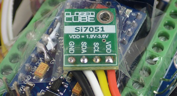
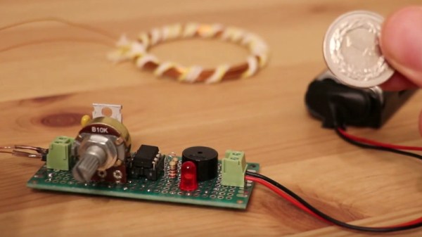
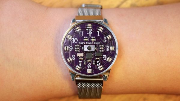
As [Chris O’Riley] relates, the watch he built for his son [Vlad] started out as a simple timer for daily toothbrushing, a chore to which any busy lad pays short shrift unless given the proper incentive. That morphed into an idea for a general purpose analog timepiece with LEDs taking the place of hands. [Chris] decided that five-minute resolution was enough for a nine-year-old, which greatly reduced the number of LEDs needed. An ATtiny841 tells a 28-channel I2C driver which LEDs to light up, and an RTC chip keeps [Vlad] on schedule. The beautiful PCB lives inside a CNC machined aluminum case; we actually commented to [Chris] that the acrylic prototype looked great by itself, but [Vlad] wanted metal. The watch has no external buttons; rather, the slightly flexible polycarbonate crystal bears against a PCB-mounted pushbutton to control functions.

With a snappy wristband, [Vlad] will be rolling fancy on the schoolyard. It’s a great looking piece that needed a wide range of skills to execute, as all watches do. Check out some other watch builds, like this lovely pure analog, another digital-analog hybrid, or this pocket watch that packs an Enigma machine inside.

Continue reading “Simple Timer Evolves Into Custom Kid’s Watch”

Multiple OLEDs? Save Pins By Sharing The I2C Clock

Inexpensive OLED displays with I2C interfaces abound, but there is a catch: they tend to be stuck on I2C address 0x3C. Some have a jumper or solder pads to select an alternate (usually 0x3D), but they lack any other method. Since an I2C bus expects every device to have a unique address, this limits the number of displays per bus to one (or two, at best.) That is all still true, but what [Larry Bank] discovered is a way to get multiple OLED displays working with considerably fewer microcontroller pins than usually needed.

While bit-banging I2C to host one display per bus on the same microcontroller, an idea occurred to him. The I2C start signal requires both clock (SCL) and data (SDA) to be brought low together, but what would happen if the displays shared a single clock line? To be clear, each OLED would — logically speaking — still be on its own I2C bus with its own data line, but they would share a clock signal. Would a shared clock cause attached devices to activate unintentionally?

A quick test consisting of four OLED displays (all with address 0x3C) showed that it was indeed possible to address each display with no interference if they shared a clock. Those four individually controlled displays needed only five I/O lines (four SDA, one shared SCL) instead of eight. The Multi_OLED library is available on GitHub, and in case it is useful for devices other than OLED displays, bit-banged I2C with support for shared clock lines is available separately.

There’s more to do with OLEDs than get clever with signals: check out these slick number-change animations, and that even looks to be a project that could benefit from a few saved GPIO pins, since it uses one small display per digit.

Common Chemicals Combine To Make Metallic Sodium

There’s no debating that metallic sodium is exciting stuff, but getting your hands on some can be problematic, what with the need to ship it in a mineral oil bath to keep it from exploding. So why not make your own? No problem, just pass a few thousand amps of current through an 800° pot of molten table salt. Easy as pie.

Thankfully, there’s now a more approachable method courtesy of this clever chemical hack that makes metallic sodium in quantity without using electrolysis. [NurdRage], aka [Dr. N. Butyl Lithium], has developed a process to extract metallic sodium from sodium hydroxide. In fact, everything [NurdRage] used to make the large slugs of sodium is easily and cheaply available – NaOH from drain cleaner, magnesium from fire starters, and mineral oil to keep things calm. The reaction requires an unusual catalyst – menthol – which is easily obtained online. He also gave the reaction a jump-start with a small amount of sodium metal, which can be produced by the lower-yielding but far more spectacular thermochemical dioxane method; lithium harvested from old batteries can be substituted in a pinch. The reaction will require a great deal of care to make sure nothing goes wrong, but in the end, sizable chunks of the soft, gray metal are produced at phenomenal yields of 90% and more. The video below walks you through the whole process.

It looks as though [NurdRage]’s method can be scaled up substantially or done in repeated small batches to create even more sodium. But what do you do when you make too much sodium metal and need to dispose of it? Not a problem.

Continue reading “Common Chemicals Combine To Make Metallic Sodium”

Blink An LED On The Internet Of Things

Blinking an LED is generally considered the hardware equivalent of the classic “Hello World” project. It’s a quick and simple test to show that you’ve got the basics worked out, and a launching point for bigger and better things. So why should it be any different in this glorious new Internet of Things era?

The “WiFi HDD LED” created by [Limbo] is essentially just that, a status LED that can be triggered remotely thanks to the WiFi capability of the ever-popular ESP8266. Don’t think there’s much use for a wireless LED that blinks when your computer’s hard drive is thrashing around? Maybe not, but it’s definitely worth checking out if you’re looking for a good way to get your feet wet in the world of ESP hacking.

On the hardware side, this is exactly what you’d expect: an LED hanging off the digital pin of an ESP8266 module. If you go with the bare ESP-01 like [Limbo], things are somewhat more complex due to the need for a voltage regulator, but if you’re using one of the more common ESP development boards then there’s nothing else you need to add. Really, as a proof of concept you could even use the built-in LED on those boards.

As you might imagine, this project is more about the software than the hardware. The code on both sides of the equation has been released as open source for your hacking pleasure, and is more capable than you’d probably expect. The LED is actually an extension of a system activity monitor that [Limbo] had previously developed and includes a binding function to make sure you’re talking to the right blinking ESP. It’s probably overkill for many purposes, but it’s a good example of how to do more robust UDP connections than we’re used to seeing.

This project is one of many that prove there’s more than one way to accomplish a particular goal, and that there’s something to be learned from even the most eccentric of hacks.

Continue reading “Blink An LED On The Internet Of Things”

The No-Parts Temperature Sensor In Your Arduino

[Edward], creator of the Cave Pearl project, an underwater data logger, needed a way to measure temperature with a microcontroller. Normally, this problem is most easily solved by throwing a temperature sensor on the I2C bus — these sensors are cheap and readily available. This isn’t about connecting a temperature sensor in your Arduino. This build is about using the temperature sensor in your clock.

The ATMega328p, the chip at the heart of all your Arduino Uno clones, has within it a watchdog timer that clicks over at a rate of 110 kHz. This watchdog timer is somewhat sensitive to temperature, and by measuring this temperature sensor you can get some idea of the temperature of the epoxy blob that is a modern microcontroller. The trick is calibrating the watchdog timer, which was done with a homemade ‘calibration box’ in a freezer consisting of two very heavy ceramic pots with a bag of rice between them to add thermal mass (you can’t do this with water because you’re putting it in a freezer and antique crocks are somewhat valuable).

By repeatedly taking the microcontroller through a couple of freeze-thaw cycles, [Edward] was able to calibrate this watchdog timer to a resolution of about 0.0025°C, which is more than enough for just about any sensor application. Discussions of accuracy and precision notwithstanding, it’s pretty good.

This technique measures the temperature of the microcontroller with an accuracy of 0.005°C or better, and it’s using it with just the interrupt timer. That’s not to say this is the only way to measure the temperature of an ATMega; some of these chips have temperature sensors built right into them, and we’ve seen projects that use this before. However, this documented feature that’s clearly in the datasheet seems not to be used by many people.

Thanks [jan] for sending this in.

The FAA Mandates External Registration Markings For Drones

Drone fliers in the USA must soon display their registration markings on the exterior of their craft, rather than as was previously acceptable, in accessible interior compartments. This important but relatively minor regulation change has been announced by the FAA in response to concerns that malicious operators could booby-trap a craft to catch investigators as they opened it in search of a registration. The new ruling is effective from February 25th, though they are inviting public comment on it.

As airspace regulators and fliers across the world traverse the tricky process of establishing a safe and effective framework for multirotors and similar craft we’ve seen a variety of approaches to their regulation, and while sometimes they haven’t made complete sense and have even been struck down in the courts, the FAA’s reaction has been more carefully considered than that in some other jurisdictions. Rule changes such as this one will always have their detractors, but as an extension of a pre-existing set of regulations it is not an unreasonable one.

It seems inevitable that regulation of multirotor flight will be a continuing process, but solace can be taken at the lower end of the range. A common theme across the world seems to be a weight limit of 250 g for otherwise unrestricted and unregistered craft, and the prospects for development in this weight category in response to regulation are exciting. If a smaller craft can do everything our 2 kg machines used to do but without the burden of regulation, we’ll take that.

An ATtiny Metal Detector

A metal detector used to be an entirely analogue instrument, an oscillator whose frequency changed with the inductance of its sense coil when a piece of metal approached. [Łukasz Podkalicki] shows us a more sophisticated machine, but with judicious use of an ATtiny 13 it is not a complex one.

A pulsed induction metal detector induces a current spike in its search coil, and times the decay of the resulting oscillation. The coil is part of a resonant circuit with a capacitor, and any metal in its field will change its resonant frequency. In [Łukasz]’s design the ATtiny13 fires a pulse at his coil using a MOSFET, and the voltages at the coil are sensed by an analogue pin through an appropriate clamp circuit. His software does the timing, and sounds a buzzer upon metal detection. It’s a deliciously simple implementation, and while as he shows us in the video below the break its relatively small coil is more suited to detecting coins or wires behind the drywall than locating lost hoards, there is probably ample scope for further experimentation.

This isn’t the first project from [Łukasz] that has found its way into these pages, his history with the ATtiny13 goes back a few years.

Continue reading “An ATtiny Metal Detector”