Pocket Sized Arduino Calculator Makes A Great First Project

We’ve all got calculators on our phones, in our web browsers, and even in the home “assistant” that’s listening in on your conversations all day on the off chance you blurt out a math question is can solve for you. The most hardcore among us might even still have a real calculator kicking around. So in that light, building your own DIY calculator might not seem too exciting. But we can’t deny this Arduino calculator project by [Danko Bertović] would look good sitting on the bench.
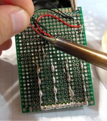
In the video after the break, [Danko] walks us through the creation of the calculator, from placing all the through-hole components to writing the code that pulls it all together. Special attention is given to explaining the wiring, making this is a good project for those just getting started on their digital hacking journey. It also helps that the whole thing is put together on perfboard with jumper wires; no PCB fabrication required for this one.

For the user interface, [Danko] is using an array of 17 tactile switches for the keyboard and a very crisp 128×32 I2C OLED display. Beyond the battery, a crystal, and a handful of passive components, that’s about all the support hardware it takes to put this project together. You don’t even need an enclosure: a second piece of perfboard and some standoffs are used to sandwich the battery and fragile wiring inside.

Of course, the star of the show is the ATmega328P microcontroller, which is mounted in a place of honor right under the OLED screen. The chip gets programmed in an Arduino Uno and then transplanted into the calculator, a neat trick if you don’t have a dedicated programmer handy. Given how cheap Arduino clones can be had online, this is becoming a more common practice.

The construction of this calculator reminds us a bit of the DIY Sinclair scientific calculator we looked at over the summer. But if you want to see the peak of homebrew calculator technology, this Raspberry Pi powered build is tough to beat.

Continue reading “Pocket Sized Arduino Calculator Makes A Great First Project”

Warnings Are Your Friend – A Code Quality Primer

If there’s one thing C is known and (in)famous for, it’s the ease of shooting yourself in the foot with it. And there’s indeed no denying that the freedom C offers comes with the price of making it our own responsibility to tame and keep the language under control. On the bright side, since the language’s flaws are so well known, we have a wide selection of tools available that help us to eliminate the most common problems and blunders that could come back to bite us further down the road. The catch is, we have to really want it ourselves, and actively listen to what the tools have to say.

We often look at this from a security point of view and focus on exploitable vulnerabilities, which you may not see as valid threat or something you need to worry about in your project. And you are probably right with that, not every flaw in your code will lead to attackers taking over your network or burning down your house, the far more likely consequences are a lot more mundane and boring. But that doesn’t mean you shouldn’t care about them.

Buggy, unreliable software is the number one cause for violence against computers, and whether you like it or not, people will judge you by your code quality. Just because Linus Torvalds wants to get off Santa’s naughty list, doesn’t mean the technical field will suddenly become less critical or loses its hostility, and in a time where it’s never been easier to share your work with the world, reliable, high quality code will prevail and make you stand out from the masses.

Continue reading “Warnings Are Your Friend – A Code Quality Primer”

Tilt-Rotor Plane Needs Flight Controller Hack To Get Airborne

Part of the charm of quadcopters is the challenge that building and flying them presents. In need of complex sensors and computational power to just get off the ground and under tremendous stresses thanks to their massively powerful motors, they often seem only barely controlled in flight. Despite these challenges, quadcopter flight has been reduced to practice in many ways, leaving hobbyists in search of another challenge.

[Tom Stanton] is scratching his creative itch with this radio-controlled tilt-rotor airplane that presents some unique problems and opportunities. Tilt-rotor planes are, as the name implies, able to swivel their propellors and transition them from providing forward thrust to providing verticle lift. With the rotors providing lift, the aircraft is able to hover and perform vertical take-off and landing (VTOL); switched to thrust mode, wings provide the lift for horizontal flight.

[Tom]’s realization of this design seems simple – a spar running through the wing holding BLDC motors and props is swiveled through 90° by a servo to transition the aircraft. Standard control surfaces on the wings and tail take care of horizontal flight. Actually getting an off-the-shelf flight controller to deal with the transitions was tricky. [Tom] ended up adding an Arduino to intercept the PWM signals the flight controller normally sends directly to the servos and speed controls to provide the coordination needed for a smooth transition. Full details in the video below, and some test flights which show that an RC VTOL is anything but a beginner’s plane.

[Tom] is proving himself to be quite the Renaissance man these days. Between air-powered piston engines, over-balance trebuchets, and popping the perfect wheelie, he seems to have covered all the bases and done his best to keep our tip line stocked.

Continue reading “Tilt-Rotor Plane Needs Flight Controller Hack To Get Airborne”

Welding Robot Takes On A Hot, Dirty, Dangerous Job

They used to say that robots would take over the jobs too dirty or dangerous for humans. That is exactly what [Joel Sullivan] had in mind when he created this welding robot. [Joel] designed the robot for the OSB industry. No, that’s not a new operating system, it’s short for Oriented Strand Board. An engineered lumber, OSB is made of strands (or chips) of wood. It’s similar to plywood but doesn’t require large thin sheets of lumber. To make a panel of OSB, a 5-inch thick matt of wood chips is mixed with glue and compressed down to 5/16″ at 7500 PSI and 400° F.

The presses used to make OSB are a massively parallel operation. 20 or more boards can be pressed at once. Thy press is also a prime area for damage. A nut or bolt hidden in the wood will dig into the press, causing a dent which will show up on every sheet which passes through that section. The only way to fix the press is to shut it down, partially dismantle it, and fill the void in with a welder. [Joel’s] robot eliminates most of the downtime by performing the welding on a still hot, still assembled press.

The robot looks like it was inspired by BattleBots, which is fitting as the environment it works in is more like a battleground. It’s a low, wide machine. In the front are two articulated arms, one with a welder, and one with a die grinder. The welder fills any voids in the press platen, and the die grinder grinds the fresh welds flat.  An intel NUC controls things, with plenty of motor drives, power supplies, and relays on board.

[Joel’s] bot is tethered, with umbilicals for argon, electricity and compressed air. Air travels through channels throughout the chassis and keeps the robot cool on the hot press. Everything is designed for high temperatures, even the wheels. [Joel] tried several types of rubber, but eventually settled on solid aluminum wheels. The ‘bot doesn’t move very fast, so there is plenty of traction. Some tiny stepper motors drive the wheels. When it’s time to weld, pneumatic outriggers lock the robot in place inside the narrow press.

Cameras with digital crosshairs allow the operator to control everything through a web interface. Once all the parameters are set up, the operator clicks go and sparks fly as the robot begins welding.

If you’re into seriously strong robots, check out trackbot, or this remote-controlled snow blower!

Continue reading “Welding Robot Takes On A Hot, Dirty, Dangerous Job”

An OpenSCAD Mini-ITX Computer Case

We’re no strangers to 3D printed enclosures here at Hackaday. From the plethora of printed Raspberry Pi cases out there to custom enclosures for electronic projects, small plastic boxes turn out to be an excellent application for desktop 3D printing. But as printers get bigger and filament gets cheaper, those little boxes don’t always need to be so little. We aren’t talking about running off boxes for your sneaker collection either, if you’ve got the time and the print volume, you could whip up an enclosure for your PC.

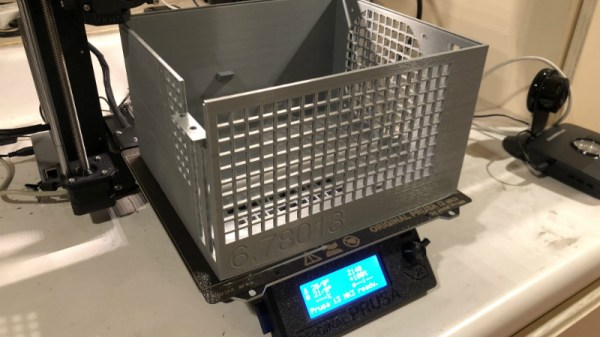
[Nirav Patel] writes in to share his impressive 3D printed Mini-ITX computer case project, which would be a neat enough trick in its own right, but he took the concept one step farther and made it a parametric design in OpenSCAD. This allows the user to input their particular hardware configuration and receive STL files for a bespoke case. The list of supported hardware isn’t that long yet, but with the OpenSCAD code up on GitHub and released under the BSD license, hopefully the community can improve on that as time goes on.

To keep things simple (and strong), [Nirav] implemented what he refers to as a “bucket” design. The majority of the case is a single print, which does take a long time (just shy of 40 hours on his Prusa i3 MK3), but nearly eliminates any post-printing assembly. Only the optional feet and the lid need to be printed separately. Threaded inserts are used throughout the design for mounting hardware, so you don’t run the risk of blowing out the printed holes during hardware changes or upgrades.

A particularly neat feature, and a testament to the power of OpenSCAD, is the fact that the case’s internal volume is calculated and embossed into the side of the design. Does this have any practical purpose? Not exactly, but [Nirav] thought it would be appealing to the Mini-ITX case modding community which apparently measures their accomplishments in liters of volume.

We’ve seen a 3D printed computer case before, but it used acrylic sheets and couldn’t be made without a large format printer. There’s something to be said for a project that can be completed on the hacker community’s favorite printer.

A QR Code, Step By Step

We should all be familiar with QR codes, those blocky printed patterns containing encoded text, URLs, or other data. A few years ago they were subject to their own cloud of hype, but now they have settled down in their niche of providing a handy route for a smartphone owner to reach a website without having to type an address.

Have you ever wondered how they work? There are plenty of dry technical guides out there, but if they’re not your thing you might find [Nayuki]’s step-by-step guide to be of interest. It explains the encoding and error checking bit generation process before starting on the familiar three-squares pattern and timing bars of the QR code itself. The really interesting part comes with its explanation of overlays, a set of repeating patterns that are added to the final data segment, and how the pattern used is chosen to minimise penalties due to large blocks of the same colour in the final piece. The chances are most of us will never have to create a QR code from scratch, but it is this type of fascinating technical general knowledge that makes guides like this such an interesting read.

QR codes have appeared in quite a few projects here over the years, but the one we find particularly amusing is this project to hack them by changing one QR into another.

Via Hacker News.

Homebrew Attachment Turns Angle Grinder Into Slimline Belt Sander

If there’s a small power tool as hackable as the angle grinder, we haven’t found it yet. These versatile tools put a lot of power in the palm of your hand, and even unhacked they have a huge range of functionality, from cutting to grinding to polishing and cleaning, just by choice of what goes on the arbor.

With a simple homebrew attachment, [Darek] turned his angle grinder into a micro-belt sander that’s great for those hard-to-reach places. The attachment that clamps where the disc guard normally lives adds a drive roller to the grinder’s arbor; idler rollers ride on the end of a small pneumatic spring that keeps the belt under tension. The belts themselves are cut down from wider sanding belts, and the attachment can take belts of various widths. And best of all, he did it all without any fancy machine tools. No lathe? No problem – the drive roller was ground to the proper crowned profile needed to keep belts centered using the angle grinder itself. The only problem we see is that the attachment can’t be easily removed from the grinder, but that’s OK. Grinders are like potato chips, after all – you can’t stop at one.

This isn’t [Darek]’s first angle grinder hacking rodeo, of course. And if you’re looking for inspiration on how to hack yours, look no further: a floor sander, a precision surface grinder, or even an e-bike can be built.

Continue reading “Homebrew Attachment Turns Angle Grinder Into Slimline Belt Sander”