Analyzing Hobby Motors With An Oscilloscope

We always like finding new excuses reasons to use our test equipment, so we couldn’t help but be intrigued by this tip from [Joe Mosfet]. He uses the ever-popular Rigol DS1054Z to demonstrate the differences between a handful of brushless motors when rotated by his handheld drill at a constant RPM. Not only is he able to identify a blown motor, but it allows him to visualize their specifications which can otherwise seem a bit mystifying.

One wire from each motor is used as the ground, and channels one and two are connected to the remaining wires. Despite the DS1054Z having four channels, [Joe] is actually only using two of them here. The third channel being displayed is a virtual channel created by a math function on the scope.

After wiring them up, each motor got put into the chuck of his drill and spun up to 1430 RPM. The resulting waveforms were captured, and [Joe] walks us through each one explaining what we’re seeing on the scope.

The bad motor is easy to identify: the phases are out of alignment and in general the output looks erratic. Between the good motors, the higher the Kv rating of the motor, the lower voltage is seen on the scope. That’s because Kv in the context of brushless motors is a measurement of how fast the motor will spin for each volt. The inverse is also true, and [Joe] explains that if he could spin his 2450Kv motor at exactly 2450 RPM, we should see one volt output.

Beyond demonstrating the practical side of Kv ratings, [Joe] also theorizes that the shape of the wave might offer a glimpse into the quality of the motor’s construction. He notes his higher end motors generate a nice clean sine wave, while his cheaper ones show distortion at the peaks. An interesting note, though he does stress he can’t confirm there’s a real-world performance impact.

Last year we featured a similar method for identifying bad brushless motors using a drill press and an oscilloscope, but we liked that [Joe] went through the trouble of testing multiple motors and explaining the differences in their output.

[via /r/multicopter]

How To Control The Lights With A TV Remote

In this day and age of the Internet of Things and controlling appliances over the internet, the idea of using an old-fashioned television remote to do anything feels distinctly 2005. That doesn’t mean it’s not a valid way to control the lights at home, and [Atakan] is here to show us how it’s done.

To the experienced electronics maker, this is yesterday’s jam, but [Atakan] goes to great lengths to hash out the whole process from start to finish, from building the circuitry to switch the lights through to the code necessary to make a PIC do your bidding. It’s rare to see such a project done with a non-Arduino platform, but rest assured, such things do exist. There’s even some SPICE simulation thrown in for good measure, if you really want to get down to the nitty-gritty.

Perhaps the only thing missing from the writeup is a primer on how to execute the project safely, given that it’s used with a direct connection to live mains wiring. We’d love to hear in the comments about any changes or modifications that would be necessary to ensure this project doesn’t hurt anyone or burn an apartment complex down. Sometimes you can switch lights without a direct connection to the mains, however – like this project that interfaces mechanically with a standard light switch.

Repairs You Can Print: Better Cable Splicing With 3D Printed Parts

A while back, [Marius] was faced with a problem. A friend of his lives in the middle of a rainforest, and a microphone was attacked by a dirty, greasy rat. The cable was gnawed in half, and with it went a vital means of communication with the outside world. The usual way of fixing a five- or six-conductor cable is with heat shrink, lineman’s splices, insulating tape, and luck. [Marius] needed something better than that, so he turned to his 3D printer and crafted his own wire splice enclosure.

The microphone in question is a fancy Jenal jobbie with a half-dozen or so conductors in the cable. A junction box was the obvious solution to this problem, and a few prototypes, ranging from rectangular to fancy oval boxes embossed with a logo were spat out on a 3D printer. These junction boxes have holes on either end, and when the cable ends are threaded through these holes, the wires can be spliced, soldered, and insulated from each other.

This microphone had to hold up to the rigors of the rainforest and rats, so [Marius] had to include some provisions for waterproofing. This came in the form of a hot glue gun; just fill the junction box with melted hot glue, pop the cover on, and just wait for it to cool. Like all good repairs, it works, and by the time this repair finally gives out, something else in the microphone is sure to go bad.

It’s a great repair, and an excellent example of how a 3D printer can make repairs easy, simple, cheap, and almost as good as the stock part. You can check out a few videos of the repair below.

Continue reading “Repairs You Can Print: Better Cable Splicing With 3D Printed Parts”

Retrotechtacular: AM Radios, Core Memory, And Color TV, What Was Hot In Chips In ’73

As part of writing tech stories such as those we feature here at Hackaday, there is a huge amount of research to be done.  We trawl through pages and pages of obscure blogs, videos, and data sheets. Sometimes we turn up resources interesting enough that we file them away, convinced that they contain the nucleus of another story at some point in the future.

Today’s topic of entertainment is just such a resource, courtesy of the Internet Archive. It’s not a video as we’d often provide you in a Retrotechtacular piece, instead it’s the February 1973 edition of the Fairchild Semiconductor Linear Integrated Circuits Catalog. Books like this one that could be had from company sales representatives were highly prized in the days before universal Internet access to data sheets, and the ink-on-paper datasheets within it provide a fascinating snapshot of the integrated electronics industry as it was 45 years ago.

The first obvious difference between then and now is one of scale, this is a single volume containing Fairchild’s entire range. At 548 pages it wouldn’t have been a slim volume by any means, but given that Fairchild were at the time one of the big players in the field it is unimaginable that the entire range of a 2018 equivalent manufacturer could be contained in the same way. Given that the integrated circuit was at the time an invention barely 15 years old, we are looking at an industry still in relative infancy.

The catalog has a series of sections with familiar headings: Operational amplifiers, comparators, voltage regulators, computer/interface, consumer, and transistor/diode arrays with analog switches. Any modern catalog will have similar headings, and there are even a few devices you will find have survived the decades. The μA741 op-amp (page 64) from its original manufacturer has not yet become a commodity product here, and it sits alongside familiar devices such as the μA7800 series (page 201) or μA723 (page 194) regulators.

Continue reading “Retrotechtacular: AM Radios, Core Memory, And Color TV, What Was Hot In Chips In ’73”

3D-Printed Punch And Die Stand Up To Steel

When you think of machine tooling, what comes to mind might be an endmill made of tungsten carbide or a punch and die made of high-speed steel. But surely there’s no room in the machine tool world for 3D-printed plastic tools, especially for the demanding needs of punching parts from sheet metal.

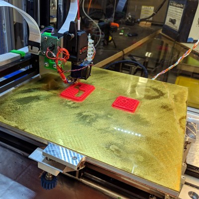
As it turns out, it is possible to make a 3D-printed punch and die set that will stand up to repeated use in a press brake. [Phil Vickery] decided to push the tooling envelope to test this, and came away pleasantly surprised by the results. In fairness, the die he used ended up being more of a composite between the carbon-fiber nylon filament and some embedded metal to reinforce stress points in the die block. It looks like the punch is just plastic, though, and both were printed on a Markforged Mark 2, a printer specifically designed for high-strength parts. The punch and die set were strong enough to form 14-gauge sheet steel in a press brake, which is pretty impressive. The tool wasn’t used to cut the metal; the blanks were precut with a laser before heading to the press. But still, having any 3D-printed tool stand up to metal opens up possibilities for rapid prototyping and short production runs.

No matter what material you make your tooling out of, there’s a lot to know about bending metal. Check out the basics in our guide to the art and science of bending metal.

Continue reading “3D-Printed Punch And Die Stand Up To Steel”

Whatever Happened To The Desktop Computer?

If you buy a computer today, you’re probably going to end up with a laptop. Corporate drones have towers stuffed under their desks. The cool creative types have iMacs littering their open-plan offices. Look around on the online catalogs of any computer manufacturer, and you’ll see there are exactly three styles of computer: laptops, towers, and all-in-ones. A quick perusal of Newegg reveals an immense variety of towers; you can buy an ATX full tower, an ATX mid-tower, micro-ATX towers, and even Mini-ITX towers.

It wasn’t always this way. Nerds of a sufficient vintage will remember the desktop computer. This was, effectively, a tower tilted on its side. You could put your monitor on top, negating the need for a stack of textbooks bringing your desktop up to eye level. The ports, your CD drive, and even your fancy Zip drive were right there in front of you. Now, those days of desktop computers are long gone, and the desktop computer is relegated to history. What happened to the desktop computer, and why is a case specifically designed for a horizontal orientation so hard to find?

Continue reading “Whatever Happened To The Desktop Computer?”

Hot rod camera dolly

Slow Down That Hot Rod Camera Dolly

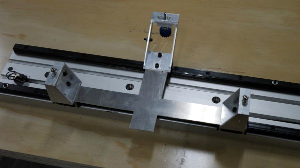
[Eric Strebel]  uses a small homemade vehicle with his camera mounted on it to get great tracking shots for the intros to his videos. If the movement is slow enough then the effect is quite professional looking. But he wanted it eight times slower. We not only like the simple way he did it, along with how he machined parts for it, but the result makes it look like a hot rod, hence his name for it, the dolly hot rod. He also has an elegant mechanism for disengaging the motor while he repositions the dolly.

Machining Bondo body filler cylinder

The are many ways to slow down a rotation. We’re assuming he was already at the minimum speed for the vehicle’s 8 RPM motor transmission and electronic speed controller. Gears or pulleys would probably be the next options. But [Eric] went even simpler, switching from roller blade wheels to larger diameter scooter wheels.

As simple as that sounds though, it led to that age-old conundrum, how to attach the wheels to the vehicle. The axle is made up of PVC tubes. So he machined square the ends of some PVC plugs and bolted the plugs to the wheel bearings. That left only to push the PVC plugs into the axle’s tubes. There are a number of ways he could have machined the PVC plugs, and the full explanation of the one he chose is best left to his video below. But basically, it involved first machining a Bondo body filler cylinder with a bolt embedded in it and then using the cylinder to hold onto the PVC plug while he machined that.

Continue reading “Slow Down That Hot Rod Camera Dolly”