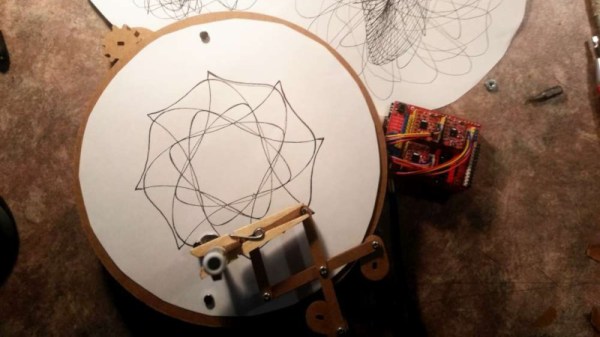
Hacking A Pint-Sized Mercedes

[Jonas] bought an electric Mercedes “ride on” toy for his one-year-old son. At least that’s his story. However, the vehicle has become a target for dad’s obsession with hacking and he’s already done quite a few upgrades. Even better, he did quite a bit of analysis on what’s already there. He isn’t done, but he’s promised quite a bit in the next installment which isn’t out yet.

The original car can take a driver or it can use remote control. [Jonas] has an ambitious list of ideas, some of which are still not complete:

  • Speed along with softer acceleration and braking
  • Improve the radio controller
  • Proper rubber tires
  • Proper stereo system
  • Individual brake disks on the front wheels
  • Improved horn
  • Proper seat belt or maybe even a new seat

Continue reading “Hacking A Pint-Sized Mercedes”

Clever Approach To Stylus Alignment

Digitally stored music is just data. But not long ago, music was analog and required machines with moving parts. If you have never owned a record player, you at least know what they look like, now that there’s a(nother) vinyl revival. What you may not be aware of is that the player’s stylus needs to be aligned. It makes sense, that hypersensitive needle can’t be expected to perform well if it’s tearing across a record like a drift racer.

There are professional tools for ensuring alignment, but it’s not something you’ll need each day. [Ali Naci Erdem] shows us his trick for combining a printable template with a mirror to get the same results without the professional tool costs. Instead of ordinary printer paper, he prints the template on a piece of clear plastic and lays it across a small mirror. These are both items which can be picked up at a hobby store, which is not something we can say about a record player mirror protractor.

We love music hacks like this informative introduction to circuit bending, the wonderful [Martin] from Wintergatan, or if you want to get weird, an organ made from Furbies.

What’s Inside A Neonode Laser Sensor?

Every once in a while, you get your hands on a cool piece of hardware, and of course, it’s your first instinct to open it up and see how it works, right? Maybe see if it can be coaxed into doing just a little bit more than it says on the box? And so it was last Wednesday, when I was at the Embedded World trade fair, and stumbled on a cool touch display floating apparently in mid-air.

The display itself was a sort of focused Pepper’s Ghost illusion, reflected off of an expensive mirror made by Aska3D. I don’t know much more — I didn’t get to bring home one of the fancy glass plates — but it looked pretty good. But this display was interactive: you could touch the floating 2D projection as if it were actually there, and the software would respond. What was doing the touch response in mid-air? I’m a sucker for sensors, so I started asking questions and left with a small box of prototype Neonode zForce AIR sensor sticks to take apart.

The zForce sensors are essentially an array of IR lasers and photodiodes with some lenses that limit their field of view. The IR light hits your finger and bounces back to the photodiodes on the bar. Because the photodiodes have a limited angle over which they respond, they can be used to triangulate the distance of the finger above the display. Scanning quickly among the IR lasers and noting which photodiodes receive a reflection can locate a few fingertips in a 2D space, which explained the interactive part of the floating display. With one of these sensors, you can add a 2D touch surface to anything. It’s like an invisible laser harp that can also sense distance.

The intended purpose is fingertip detection, and that’s what the firmware is good at, but it must also be the case that it could detect the shape of arbitrary (concave) objects within its range, and that was going to be my hack. I got 90% of the way there in one night, thanks to affordable tools and free software that every hardware hacker should have in their toolbox. So read on for the unfortunate destruction of nice hardware, a tour through some useful command-line hardware-hacking tools, and gratuitous creation of animations from sniffed SPI-like data pulled off of some test points.

Continue reading “What’s Inside A Neonode Laser Sensor?”

The M1 NerfBot: When Prototypes Evolve

What do you get when you cross a self-taught maker with an enthusiasm for all things Nerf? A mobile nerf gun platform capable of 15 darts per second. Obviously.

The M1 NerfBot built by [GrimSkippy] — posting in the ‘Let’s Make Robots’ community — is meant to be a constantly updating prototype as he progresses in his education. That being the case, the progress is evident; featuring two cameras — a webcam on the turret’s barrel, and another facing forward on the chassis, a trio of ultrasonic sensors, controlled by an Xbox 360 controller, and streaming video to a webpage hosted on the M1 itself, this is no mere beginner project.

Perhaps most compelling is how the M1 tracks its targets. The cameras send their feeds to the aforementioned webpage and — with a little reorganization — [GrimSkippy] accesses the the streams on an FPV headset-mounted smartphone. As he looks about, gyroscopic data from the phone is sent back to the M1, translating head movement into both turret and chassis cam movement. Check it out!

Continue reading “The M1 NerfBot: When Prototypes Evolve”

Retrotechtacular: A Very British MagLev

When we look back to the 1970s it is often in a light of somehow a time before technology, a time when analogue was still king, motor vehicles had carburettors, and telephones still had rotary dials.

In fact the decade had a keen sense of being on the threshold of an exciting future, one of supersonic air travel, and holidays in space. Some of the ideas that were mainstream in those heady days didn’t make it as far as the 1980s, but wouldn’t look out of place in 2018.

The unlikely setting for todays Retrotechtacular piece is the Bedford Levels, part of the huge area of reclaimed farmland in the east of England known collectively as the Fens. The Old Bedford River and the New Bedford River are two straight parallel artificial waterways that bisect the lower half of the Fens for over 20 miles, and carry the flood waters of the River Ouse towards the sea. They are several hundred years old, but next to the Old Bedford River at their southern end are a few concrete remains of a much newer structure from 1970. They are all that is left of a bold experiment to create Britain’s first full-sized magnetic levitating train, an experiment which succeeded in its aim and demonstrated its train at 170 miles per hour, but was eventually canceled as part of Government budget cuts.

A track consisting of several miles of concrete beams was constructed during 1970 alongside the Old Bedford River, and on it was placed a single prototype train. There was a hangar with a crane and gantry for removing the vehicle from the track, and a selection of support and maintenance vehicles. There was an electrical pick-up alongside the track from which the train could draw its power, and the track had a low level for the hangar before rising to a higher level for most of its length.

After cancellation the track was fairly swiftly demolished, but the train itself survived. It was first moved to Cranfield University as a technology exhibit, before in more recent years being moved to the Railworld exhibit at Peterborough where it can be viewed by the general public. The dream of a British MagLev wasn’t over, but the 1980s Birmingham Airport shuttle was hardly in the same class even if it does hold the honour of being the world’s first commercial MagLev.

We have two videos for you below the break, the first is a Cambridge Archaeology documentary on the system while the second is a contemporary account of its design and construction from Imperial College. We don’t take high-speed MagLevs on our travels in 2018, but they provide a fascinating glimpse of one possible future in which we might have.

It does make one wonder: will the test tracks for Hyperloop transportation break the mold and find mainstream use or will we find ourselves 50 years from now running a Retrotechtacular on abandoned, vacuum tubes?

Continue reading “Retrotechtacular: A Very British MagLev”

AM ultrasonic transmitter and receiver

AM Ultrasonic Transmitter And Receiver

Most often ultrasonic transducers are used for distance measurements, and in the DIY world, usually as a way for robots to detect obstacles. But for a weekend project, [Vinod.S] took the ultrasonic transmitter and receiver from a distance-meter module and used amplitude modulation to send music ultrasonically from his laptop to a speaker, essentially transmitting and receiving silent, modulated sounds waves.

The transmitter and receiver

For the transmitter, he turned an Arduino Pro Micro into a USB sound card which he could plug into his laptop. That outputs both the audio signal and a 40 kHz carrier signal, implemented using the Arduino’s Timer1. Those go to a circuit board he designed which modulates the carrier with the audio signal using a single transistor and then sends the result out the ultrasonic transmitter.

He took care to transmit a clear signal by watching the modulated wave on an oscilloscope, looking for over-modulation and clipping while adjusting the values of resistors located between the transistor, a 5 V from the Arduino and the transmitter.

He designed the receiver side with equal care. Conceptually the circuit there is simple, consisting of the ultrasonic receiver, followed by a transistor amplifier for the modulated wave, then a diode for demodulation, another transistor amplifier, and lastly a class-D amplifier before going to a speaker.

Due to the low 40 kHz carrier frequency, the sound lacks the higher audio frequencies. But as a result of the effort he put into tuning the circuits, the sound is loud and clear. Check out the video below for an overview and to listen to the sound for yourself. Warning: Before there’s a storm of comments, yes the video’s shaky, but we think the quality of the hack more than makes up for it.

Continue reading “AM Ultrasonic Transmitter And Receiver”

The Sensor Array That Grew Into A Robot Cat

Human brains evolved to pay extra attention to anything that resembles a face. (Scientific term: “facial pareidolia”) [Rongzhong Li] built a robot sensor array with multiple emitters and receivers augmenting a Raspberry Pi camera in the center. When he looked at his sensor array, he saw the face of a cat looking back at him. This started his years-long Petoi OpenCat project to build a feline-inspired body to go with the face.

While the name of the project signals [Rhongzhong]’s eventual intention, he has yet to release project details to the open-source community. But by reading his project page and scrutinizing his YouTube videos (a recent one is embedded below) we can decipher some details. Motion comes via hobby remote-control servos orchestrated by an Arduino. Higher-level functions such as awareness of environment and Alexa integration are handled by a Raspberry Pi 3.

The secret (for now) sauce are the mechanical parts that tie them all together. From impact-absorption spring integrated into the upper leg to how its wrists/ankles articulate. [Rongzhong] believes the current iteration is far too difficult to build and he wants to simplify construction before release. And while we don’t have much information on the software, the sensor array that started it all implies some level of sensor fusion capabilities.

Continue reading “The Sensor Array That Grew Into A Robot Cat”