Hackaday gets results! Reader [John] saw our recent Fail of the Week post about a “sand matrix printer” and decided to share his own version, a sand-dispensing dot matrix printer he built last year.
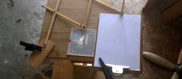
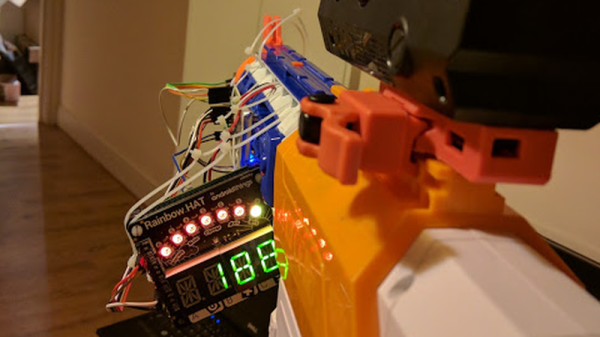
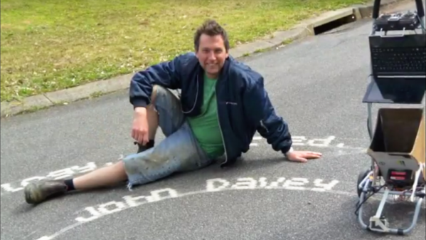
Granted, [John]’s version is almost the exact opposite of [Vjie Miller]’s failed build, which sought to make depressions in the sand to print characters. [John]’s Sandscript takes a hopper full of dry, clean sand and dispenses small piles from six small servo-controlled nozzles. The hopper is mounted on a wheeled frame, and an optical encoder on one wheel senses forward motion to determine when to open each nozzle. As [John] slowly walks behind and to the side of the cart, a line of verse is slowly drizzled out onto the pavement. See it in action in the video below.
More performance art piece than anything else, we can see how this would be really engaging, with people following along like kids after the [Pied Piper], waiting to find out what the full message is. There’s probably a statement in there about the impermanence of art and the fleeting nature of existence, but we just think it’s a really cool build.
We’ve featured other sand writers before, like this high-resolution draw bot that also dispenses sandy verses, or this literal beach-combing art bot. Guess there’s just something about sand that inspires artists and hackers alike.
Continue reading “Poetry In Motion With A Sand-Dispensing Dot Matrix Printer”