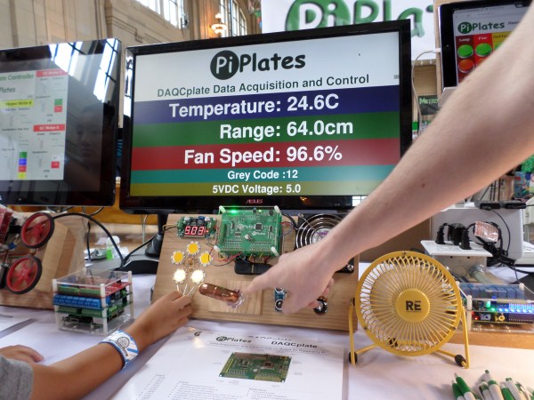
As soon as he spied the Jolly Wrencher on my shirt, [Jerry Wasinger] beckoned me toward his booth at Kansas City Maker Faire. Honestly, though, I was already drawn in. [Jerry] had set up some interactive displays that demonstrate the virtues of his Pi-Plates—Raspberry Pi expansion boards that follow the HAT spec and are compatible with all flavors of Pi without following the HAT spec. Why not? Because it doesn’t allow for stacking the boards.
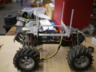
[Jerry] has developed three types of Pi-Plates to date. There’s a relay controller with seven slots, a data acquisition and controller combo board, and a motor controller that can handle two steppers or up to four DC motors. The main image shows the data acquisition board controlling a fan and some lights while it gathers distance sensor data and takes the temperature of the Faire.
The best part about these boards is that you can stack them and use up to eight of any one type. For the motor controller, that’s 16 steppers or 32 DC motors. But wait, there’s more: you can still stack up to eight each of the other two kinds of boards and put them in any order you want. That means you could run all those motors and simultaneously control several voltages or gather a lot of data points with a single Pi.
The Pi-Plates are available from [Jerry]’s site, both singly and in kits that include an acrylic base plate, a proto plate, and all the hardware and standoffs needed to stack everything together.