
Treadmill To Belt Grinder Conversion Worked Out

[Mike] had a bunch of disused fitness machines lying around. Being a skilled welder, he decided to take them apart and put them back together in the shape of a belt grinder.

In particular, [Mike] is reusing the height-adjustment guide rail of an old workout bench to build the adjustable frame that holds the sanding belt. A powerful DC motor including a flywheel was scavenged from one treadmill, the speed controller came from another. [Mike] won’t miss the workout bench: Once you’re welding a piece of steel tube dead-center on a flywheel, as happened for the grinder’s drive wheel, you may call yourself a man (or woman) of steel.

The finished frame received a nice paint job, a little switching cabinet, proper running wheels and, of course, a sanding belt. Despite all recycling efforts, about 80 bucks went into the project, which is still a good deal for a rock-solid, variable-speed belt grinder.

Apparently, disused fitness devices make an ideal framework to build your own tools: Strong metal frames, plentiful adjustment guides, and strong treadmill motors. Let us know how you put old steel to good use in the comments and enjoy [Mike’s] build documentation video below!

Continue reading “Treadmill To Belt Grinder Conversion Worked Out”
Fail Of The Week: Power Wheels Racing Series

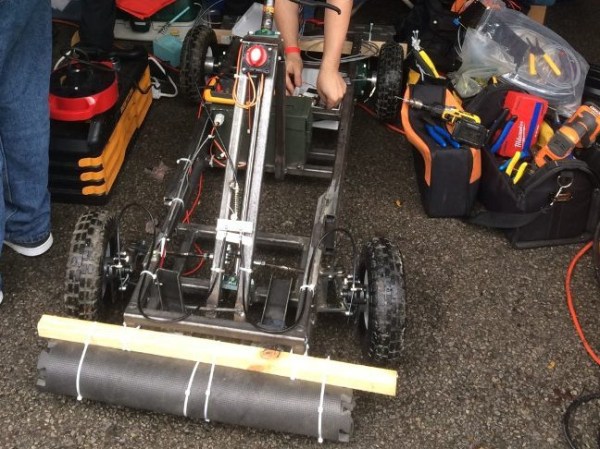
[ITMAN496] and his local HAM radio group entered the Power Wheels Racing Series with great intentions, a feeling of unlimited power, and the universal spirit of procrastination all hackers share.

It wasn’t the first time his group had worked together on something a little different, such as a robot that can deploy an antenna by climbing poles. However, this one had a time limit and they ended up trying to fit it all in the week before the race.

They had a pretty good design. [ITMAN496] had modeled the entire frame in SketchUp and even did physics simulations to get the steering just right. However, the best laid plans of mice and men often don’t fully take into account just how hard it is to get the motor drivers they bought working.

In the end, what they really needed was time to test. The setscrews couldn’t hold the motor on the shaft, the electronics needed debugging, and one of the belts was too long. The design was solid, but without time to percussively maintain the last bugs out of the system, it just wasn’t going to run.

[ITMAN496] is taking this lesson properly; he’s already planning for next year’s run, but this time he’ll have time to test. We must commend him — the build under these time constraints was still impressive. Even more so that he took the time to document everything while it was happening, and to share the story of shortfall after the fact. We’re always on the hunt for documented fails (the best way to really learn something).

Hackaday Prize Entry: $50 Foot Controlled Mouse

ALS robbed one of [C. Niggel]’s relative’s of the use of their upper body. This effectively imprisoned them in their house; ALS is bad stuff. Unfortunately too, the loss of upper body mobility meant that they couldn’t even use the computer to interact with people and the outside world. However, one day [C. Niggel] noted that the relative’s new electric wheelchair was foot controlled. Could this be adapted to a computer mouse?

He looked up commercial solutions and found them not only prohibitively expensive, but also fraught with proprietary drivers and all sorts of bad design nonsense. With all of the tools out there today there was no reason this couldn’t be quickly prototyped and sent to the relative in need.

He used a combination of conductive thread, neoprene, and velostat to build the pads themselves. The pads were balanced with some adjusting resistors in series. The signals are sent to an Adafruit Feather board which interprets them and converts it to a PS/2 standard.

The first version of the mouse used separate pads glued to a MDF board with contact cement. However this, along with some other initial design flaws, resulted in premature failure of the mouse. [C. Niggel] quickly returned to the lab and produced a new version with more robust construction and mailed it off. So far so good!

Open Design Oscilloscope Could Be (Almost) Free

If you could only own one piece of test equipment, it should probably be an oscilloscope. Then again, modern scopes often have multiple functions, so maybe that’s not a fair assertion. A case in point is the Scopefun open hardware project. The device is a capable 2-channel scope, a logic analyzer and also a waveform and pattern generator. The control GUI can work with Windows, Linux, or the Mac (see the video, below).

The hardware uses a Xilinx Spartan-6 FPGA. A GUI uses a Cypress’s EZ-USB FX2LP chip to send configuration data to the FPGA.  Both oscilloscope channels are protected for overvoltage up to +/- 50 V. The FPGA samples at 100 Mhz through a 10-bit dual analog-to-digital converter ( ADC ). The FPGA handles triggering and buffers the input before sending the data to the host computer via the USB chip. Each channel has a 10,000 sample buffer.

There are also two generator outputs with short circuit and overvoltage protection ( +/- 50 V ). Generator channels have 50 Ohm internal impedance and also operates via the GUI using the same USB chip. The FPGA generates signals at 50 Mhz using counters, algorithms, or simple waveform data and feeds a DAC.

A 16-bit digital interface can be set as inputs or outputs. The FPGA samples inputs at 100 MHz. The output voltage can be set, but inputs are 5 V tolerant.

According to the developer, you can build the scope from the information provided by using free sample chips from the various vendors, only paying for the small components and the cost of the PCB.

We’ve looked at several low-cost scope options before. Labtool even boasts some similar features.

Never Twice The Same Color: Why NTSC Is So Weird

Ever wonder why analog TV in North America is so weird from a technical standpoint? [standupmaths] did, so he did a little poking into the history of the universally hated NTSC standard for color television and the result is not only an explanation for how American TV standards came to be, but also a lesson in how engineers sometimes have to make inelegant design compromises.

Before we get into a huge NTSC versus PAL fracas in the comments, as a resident of the US we’ll stipulate that our analog color television standards were lousy. But as [standupmaths] explores in some depth, there’s a method to the madness. His chief gripe centers around the National Television System Committee’s decision to use a frame rate of 29.97 fps rather than the more sensible (for the 60 Hz AC power grid) 30 fps. We’ll leave the details to the video below, but suffice it to say that like many design decisions, this one had to do with keeping multiple constituencies happy. Or at least equally miserable. In the end [standupmaths] makes it easy to see why the least worst decision was to derate the refresh speed slightly from 30 fps.

Given the constraints they were working with, that fact that NTSC works as well as it does is pretty impressive, and quite an epic hack. And apparently inspiring, too; we’ve seen quite a few analog TV posts here lately, like using an SDR to transit PAL signals or NTSC from a microcontroller.

Continue reading “Never Twice The Same Color: Why NTSC Is So Weird”

Galaga Cabinet Is Out Of This World

Like many of us, [Alex] spent a large part of his childhood feeding coin after coin into one arcade game or another. Galaga is one of his all-time favorites, and he has wanted to build a Galaga cabinet for a long time. Once his workshop was ready for the job, it was time to cross it off the list.

The cabinet is built to 4/5 scale. This is a great size because he gets the stability and feel of a full-size machine, but it’s much easier to move it around. As you might expect, there’s Pi in the cabinet.  The display is an old TV that [Alex] found in a Dumpster. And although it works great, it would go into standby instead of powering off along with everything else. To get around this, [Alex] built an automatic remote control with an IR LED and an Arduino Diecimila. After a five-second wait, it sends the power-on code to the TV and switches the input. The TV is supposed to be in portrait mode for Galaga, but this proved to be a challenge. Changing the orientation at the Pi level resulted in poor performance and choppy sound, so he changed it at the game execution level.

We are continually impressed by the diversity of [Alex]’s builds and the care that goes into them. Who could forget his beautiful sidewalk graffiti machine or the time he showed us how to photograph stuff that’s not there? Make the jump to see a brief demonstration followed by a two-part build video.

Continue reading “Galaga Cabinet Is Out Of This World”

Robots With 3D Printed Shock Absorbing Skin

MIT’s Computer Science and Artificial Intelligence Laboratory, CSAIL, put out a paper recently about an interesting advance in 3D printing. Naturally, being the computer science and AI lab the paper had a robotic bend to it. In summary, they can 3D print a robot with a rubber skin of arbitrarily varying stiffness. The end goal? Shock absorbing skin!

They modified an Objet printer to print simultaneously using three materials. One is a UV curing solid. One is a UV curing rubber, and the other is an unreactive liquid. By carefully depositing these in a pattern they can print a material with any property they like. In doing so they have been able to print mono body robots that, simply put, crash into the ground better.  There are other uses of course, from joints to sensor housings. There’s more in the paper.

We’re not sure how this compares to the Objet’s existing ability to mix flexible resins together to produce different Shore ratings. Likely this offers more seamless transitions and a wider range of material properties. From the paper it also appears to dampen better than the alternatives. Either way, it’s an interesting advance and approach. We wonder if it’s possible to reproduce on a larger scale with FDM.