1980s Plotter Plays Flappy Bird

Should you happen to have an HP7440A or similar plotter hanging around, you could have a quick game of Flappy Bird — or Plotty Bird as [WesleyAC] calls it. Just be sure you have some blank paper. The whole thing fits in about 200 lines of Rust code and — according to the author — gets to about 20 frames per second.

Watching the thing go, it appears that it draws a random set of pipes and then traces your flight path on the same page in real time.

Continue reading “1980s Plotter Plays Flappy Bird”

Build A Plotter Using Scrap DVD Drives

Building your own CNC machine can present a series of varied challenges. There are the software considerations, but also the mechanical side of things – motors, shafts, screws and slides all need to be addressed in a working design. Of course, you can always outsource some of the work – and that’s precisely what [Daniele Tartaglia] did with this pen plotter build (Youtube link, embedded below).

It’s a capable plotter, able to nicely reproduce both graphics and text.

The build gains X and Y axes by virtue of two salvaged DVD drives. The tray mechanisms come ready to go with stepper motors and lead screws already assembled, and make a great basis for a compact plotter. A wooden frame is constructed to hold everything together. The pen is held against the paper with a rubber band which helps the ballpoint to draw a nice dark line, with a servo used as a pen retract mechanism. An Arduino Uno with a stepper driver shield is then employed to run the show.

It’s a tidy build, with neat cable management and smart design choices giving it a pleasing aesthetic. The CNC fundamentals are good, too – with minimal backlash and slop, the plotter is able to draw quite effectively. Old optical drives are a popular choice for plotter builds, as it turns out. Video after the break.

Continue reading “Build A Plotter Using Scrap DVD Drives”

Omni Wheels Move This CNC Plotter

We’ve always had a soft spot for omni wheels and the bots that move around somewhat bumpily on them. Likewise, CNC pen plotters are always a welcome sight in our tip line. But a CNC plotter using omni wheels is new, and the results are surprisingly good.

Built from the bottom of a spring-form baking pan, [lingib]’s plotter is simplicity itself. Four steppers turn the omni wheels while a hobby servo raises and lowers the pen. The controller is an Uno with a Bluetooth module for smartphone control. Translating wheel rotations into X- and Y-axis motions was not exactly trivial, and the video below shows the results. Lines are a bit wobbly, and it’s clear that the plotter isn’t hitting the coordinates very precisely. But given the somewhat compliant nature of the omni wheels, we’re surprised [lingib] got results as good as these, and we applaud the effort.

[lingib] reports the most expensive part of this $100 build was the omni wheels themselves. We suppose laser-cut MDF omni wheels could reduce the price, or even Mecanum wheels from bent metal and wood. We’re not sure either will help with the precision, though.

Continue reading “Omni Wheels Move This CNC Plotter”

Make An Impression At The Bar With A CNC Coaster Plotter

If you’re anything like us, your success with the opposite sex at the bar wasn’t much to brag about. But imagine if you had only had this compact CNC polar plotter and could have whipped up a few custom coasters for your intended’s drink. Yeah, that definitely would have helped.

Or not, but at least it would have been fun to play with. This is actually an improved version of [bdring]’s original “Polar Coaster”. Version 2 is really just a more compact and robust version of the original. The new one has a custom controller for the steppers and pen-lift servo, and everything is mounted neatly to the main PCB. Where the original used a timing belt to drive the platter, the new one uses 3D-printed helical gears, and the steppers have been replaced by slimmer motors. It even has an SD card and smartphone UI, and the coasters look pretty good.

There’s no video of the new one, but you can see its predecessor in action below and imagine the possibilities. Snap a picture and have a line art rendition of someone plotted while you’re waiting for drinks? Just remember not to take any laser engraved wooden nickels.

Continue reading “Make An Impression At The Bar With A CNC Coaster Plotter”

Maze Generator Keeps Plotter (and Kids) Busy

We can tell that [Jon Howell] is our kind of guy. After updating his vintage 1985 Hewlett-Packard plotter with WiFi and the ability to load SVG files, he obviously needed to find a bunch of stuff to run off with it. Gotta justify those hacks somehow. So he doubled down and decided support a hack with another hack by writing a maze generator to keep his plotter well fed. He was kind enough to unleash his creation on an unsuspecting Internet as an open source project, and now we all can benefit from a couple of reams worth of mazes.

The generator itself is written in Java, and should work on whatever operating system your box happens to be running thanks to the *nix and Windows wrapper scripts [Jon] provides. To create a basic maze, one simply needs to provide the script with the desired dimensions and the paper size. You can define the type of paper with either standard sizes (such as --paper a4) or in the case of a plotter with explicit dimensions (--paper 36x48in).

If you aren’t a big fan of right angles, there’s support for changing the internal geometry of the maze to use a hexagonal or triangle grid. You can even pass the program a black and white PNG “mask” which it will use as the boundaries for the maze itself, allowing for personalized puzzles of whatever shape catches your fancy. [Jon] even ran the Wrencher though his software, leading to the creation of a maze which we can neither confirm nor deny will be making an appearance on our Christmas cards this year.

Whether you need to prove to your significant other that the hours you spent fiddling with your plotter are well spent, or an easy way to entertain the junior humans in your life, you can thank [Jon] for your solution.

Vintage Plotter Turned Fruit Spectrometer

Fruit can be a tricky thing: if you buy it ripe you’ll be racing against time to eat the pieces before they turn into a mushy mess, but if you buy the ones which are a bit before their prime it’s not always easy to tell when they’re ready to eat. Do you smell it? Squeeze it? Toss it on the counter to see if it bounces? In the end you forget about them and they go bad anyway. That’s why here at Hackaday we sustain ourselves with only collected rainwater and thermo-stabilized military rations.

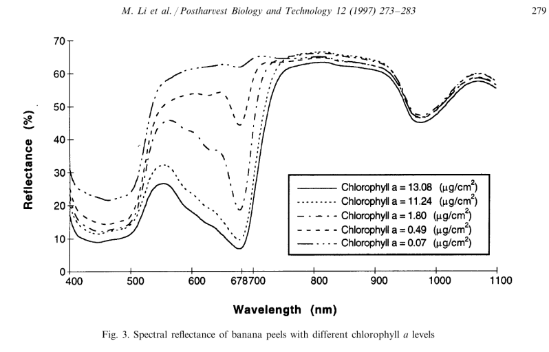
But thankfully Cornell students [Christina Chang], [Michelle Feng], and [Russell Silva] have come up with a delightfully high-tech solution to this decidedly low-tech problem. Rather than rely on human senses to determine when a counter full of fruit has ripened, they propose an automated system which uses a motorized spectrometer to scan an arrangement of fruit. The device measures the fruit’s reflectance at 678 nm, which can be used to determine the surface concentration of chlorophyll-a; a prime indicator of ripeness.

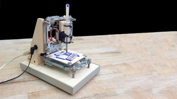
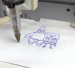
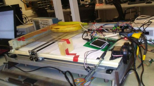
If that sounds a bit above your pay grade, don’t worry. The students were able to build a functional prototype using a 1980’s era plotter, a Raspberry Pi, and a low-cost AS7263 NIR spectral sensor from SparkFun which just so happens to have a peak responsivity of 680 nm. The scanning is performed by a PIC32MX250F128B development board with an attached TFT LCD display so the results can be easily viewed. The Raspberry Pi is used in conjunction with a Adafruit PCA9685 I2C PWM driver to control the plotter’s stepper motors. The scanning and motor control could be done with the PIC32 alone, but to save time the students decided to use the Raspberry Pi to command the PCA9685 as that was what the documentation and software was readily available for.

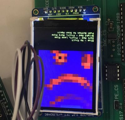
To perform a scan, the stepper motors home the AS7263 sensor module, and then passes it under the fruit which is laying on a clear acrylic sheet. Moving the length of the acrylic sheet, the sensor is able to scan not only multiple pieces of fruit but the entirety of each piece; allowing it to determine for example if a section of a banana has already turned. The relative ripeness of the fruit is displayed to the user on the LCD display as a heatmap: the brighter the color the more ripe it is.

At the end of their paper, [Christina], [Michelle], and [Russell] note that while the scanner worked well there’s still room for improvement. A more scientific approach to calculating how ripe each fruit is would make the device more accurate and take out the guess work on the part of the end user, and issues with darker colored fruit could potentially be resolved with additional calibration.

While a spectrometer might sound like the kind of equipment that only exists in multi-million dollar research laboratories, we occasionally see projects like this which make the technology much more accessible. This year we saw a compact spectrometer in the Hackaday Prize, and going a bit farther back in time we even featured a roundup of some of the most impressive spectrometer builds on Hackaday.io.

Continue reading “Vintage Plotter Turned Fruit Spectrometer”

Making PCBs With A Cutting Plotter

[LudwigLabs] is creating PCBs using copper foil and a cutting plotter (vinyl cutter). In this approach, it’s an additive process where instead of removing copper from a copper-clad board, the traces are cut out of copper foil and transferred to a solid backing surface (cardboard, fiberglass, etc.).

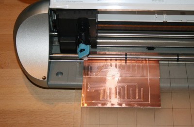
While similar to the use of copper tape laid out by hand, as covered by us last year, the big advantage of using a cutting plotter is that it allows one to create much more complicated traces similar to those you would expect to see on a factory-made PCB. Since cutting plotters translate a 2D design into very precise movements of the cutting blade, this allows for sharp angles and significantly thinner traces, allows designs from EDA software like KiCad or Altium to be quickly translated to physical boards.

Enterprising hackers might consider the possibility of using this approach to make two-sided, and even multi-layered boards. The copper is produced separately from the substrate which opens up the potential for using uncommon materials like glass or paper to host the circuits. The main limitations are the transferring of (very delicate) copper structures and creating vias without damaging the traces.

As a comparison with traditional PCB fab processes, the photo exposure and etching (or laser exposure and etching) process requires the creation of masks, UV exposing a board, etching, cleaning and so on. The simplicity of copper foil traces has led to many experimenting with this approach. Would you want to use this additive process, or are there refinements or alterations you would make?