Comparing AliExpress Vs LCSC-Sourced MOSFETs

The fake AliExpress-sourced IRFP460 MOSFETs (Credit: Learn Electronics Repair, YouTube)

These days, it’s super-easy to jump onto the World Wide Web to find purported replacement parts using nothing but the part identifier, whether it’s from a reputable source like Digikey or Mouser or from more general digital fleamarkets like eBay and AliExpress. It’s hardly a secret that many of the parts you can buy online via fleamarkets are not genuine. That is, the printed details on the package do not match the actual die inside. After AliExpress-sourced MOSFETs blew in a power supply repair by [Learn Electronics Repair], he first tried to give the MOSFETs the benefit of the doubt. Using an incandescent lightbulb as a current limiter, he analyzed the entire PSU circuit before putting the blame on the MOSFETs (IRFP460) and ordering new ones from LCSC.

Buying from a distributor instead of a marketplace means you can be sure the parts are from the manufacturer. This means that when a part says it is a MOSFET with specific parameters, it almost certainly is. A quick component tester session showed the gate threshold of the LCSC-sourced MOSFETs to be around 3.36V, while that of the AliExpress ‘IRFP460’ parts was a hair above 1.8V, giving a solid clue that whatever is inside the AliExpress-sourced MOSFETs is not what the package says it should be.

Unsurprisingly, after fitting the PSU with the two LCSC-sourced MOSFETs, there was no more magic smoke, and the PSU now works. The lesson here is to be careful buying parts of unknown provenance unless you like magic smoke and chasing weird bugs.

Continue reading “Comparing AliExpress Vs LCSC-Sourced MOSFETs”

A man in glasses and a black sweatshirt sits in front of an orange and black computer screen just below eye level at the table in front of him. His keyboard sits on the table below. He appears to be in a park as there are trees and grass in the background.

Flying Lotus Is A Framework-Powered Portable All-in-One Computer

One of the things that we love about the modern era of computing is the increasing ease by which you can roll your own custom computer, as seen with the cyberdeck phenomenon. The Flying Lotus is another awesome build in this vein.

Built around the Framework ecosystem, this device was built to suit the very specific use case of its designer, [Carlos Aldana]. He found himself traveling a lot and that the ergonomics of a laptop left a lot to be desired, especially when in the air. Add to it the fact that he has trouble typing on typical laptop keyboards for any length of time, and you can see how an ergonomic keyboard plus a laptop just doesn’t really work on a tray table.

The Flying Lotus takes the screen, modular ports, and mainboard of a Framework laptop and puts them into a single computing block that can be hung from the clever tabs at the top or mounted on a stand that puts the screen at a more ergonomically ideal height from the work surface. [Aldana] describes it as an “iMac that’s portable.” Since it doesn’t have an integrated keyboard, you can run it with whatever keyboard you like from super duper ergo to a teeny game controller sized unit.

We’ve talked about why we like Framework so much before, and if you’d like another take on a modern portable computer, how about this portable Mac mini?

Continue reading “Flying Lotus Is A Framework-Powered Portable All-in-One Computer”

Compact Driver Powers Steppers With USB-C PD

NEMA-17 steppers are (almost) a dime a dozen. They’re everywhere, they’re well-known to hackers and makers, and yet they’re still a bit hard to integrate into projects. That’s because the motor alone isn’t much use, and by the time you find or build a driver and integrate it with a microcontroller, you’ve probably expended more effort than you will on the rest of the project. This USB-C PD stepper driver aims to change that.

What caught our eye about [Josh Rogan]’s PD Stepper is his effort to make this a product rather than just a project. The driver is based on a TMC2209 for silent operation and a lot of torque thanks to the power delivery capabilities of USB-C PD. The PCB is very nicely designed and has an AS5600 rotary magnetic encoder for closed-loop operation. There’s also an ESP32-S3 on-board, so WiFi and Bluetooth operation are possible — perfect for integration into Home Assistant via ESPHome.

[Josh]’s mechanical design is top-notch, too, with a machined aluminum spacer that fits on the back of a NEMA-17 motor perfectly and acts as a heat spreader. A machined polycarbonate cover protects the PCB and makes a very neat presentation. [Josh] has kits available, or you can roll your own with the provided build files.

Continue reading “Compact Driver Powers Steppers With USB-C PD”

A Game Of Snake On A LEGO Mechanical Computer

Really, [OzzieGerff] had us at “LEGO.” But then he took it to another place entirely and built a completely mechanical, nearly 100% LEGO version of Snake. And it’s just as cool as it sounds.

Mind you, it’s a little hard to grok how this whole contraption works, which has been in the works for a while, but we’ll try to summarize as best we can. The most important aspect of this build is that there are no electronics at all — everything is done with mechanical linkages, with some Technics pneumatic components and a couple of electric motors to provide the oomph. The three main components are the input section, which consists of a two-axis joystick, a tail buffer, which keeps track of the length of the snake’s tail as gameplay progresses, and the largest component, the 16×16 display.

The joystick translates user inputs into pneumatic signals which pass through a mechanical filtering unit that prevents the head of the snake from doubling back on itself. The filtered inputs then pass into the screen reader, a complex device that probes the status of a given pixel on the display and determines the status of the snake’s head. If it touches a snake pixel, the game’s over. Hitting a blank pixel moves the head of the snake by one and takes one pixel off the end, while a food pixel extends the snake’s length.

Keeping track of the length of the snake is the job of the buffer, which uses Technics tank tracks and levers. Setting a one is done by flipping the lever to one side as it passes under the write head; a read head further down the track senses which way the lever is flipped and translates it into a pneumatic signal. The buffer has four channels, one for each possible direction the snake’s head could be moving. The signals drive a screen writer, which moves a pyramidal follower across a series of push-rods that flip the corresponding pixel on the display to show the proper icon. Simplicity itself? No, but the video below will make things a lot clearer.

It doesn’t look like [Ozzie] is quite done with this game, as he doesn’t show any actual gameplay yet. We’d love to see and hear that — we suspect it’ll make quite a racket. We’ll be keeping an eye out for this one, but while we wait, check out this rope braiding machine or watch Lego break steel.

Continue reading “A Game Of Snake On A LEGO Mechanical Computer”

Creating Customized Diffraction Lenses For Lasers

[The Thought Emporium] has been fascinated by holograms for a long time, and in all sorts of different ways. His ultimate goal right now is to work up to creating holograms using chocolate, but along the way he’s found another interesting way to manipulate light. Using specialized diffraction gratings, a laser, and a few lines of code, he explores a unique way of projecting hologram-like images on his path to the chocolate hologram.

There’s a lot of background that [The Thought Emporium] has to go through before explaining how this project actually works. Briefly, this is a type of “transmission hologram” that doesn’t use a physical object as a model. Instead, it uses diffraction gratings, which are materials which are shaped to light apart in specific ways. After some discussion he demonstrates creating diffraction gratings using film. Certain diffraction patterns, including blocking all of the light source, can actually be used as a lens as the light bends around the blockage into the center of the shadow where there can be focal points. From there, a special diffraction lens can be built.

The diffraction lens can be shaped into any pattern with a small amount of computer code to compute the diffraction pattern for a given image. Then it’s transferred to film and when a laser is pointed at it, the image appears on the projected surface. Diffraction gratings like these have a number of other uses as well; the video also shows a specific pattern being used to focus a telescope for astrophotography, and a few others in the past have used them to create the illusive holographic chocolate that [The Thought Emporium] is working towards.

Continue reading “Creating Customized Diffraction Lenses For Lasers”

A very tiny keyboard with RGB backlighting.

Tiny Custom Keyboard Gets RGB

Full-size keyboards are great for actually typing on and using for day-to-day interfacing duties. They’re less good for impressing the Internet. If you really want to show off, you gotta go really big — or really small. [juskim] went the latter route, and added RGB to boot!

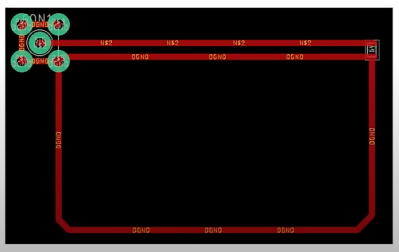
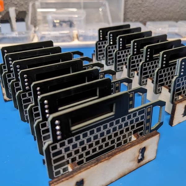
This was [juskim]’s attempt to produce the world’s smallest keyboard. We can’t guarantee that, but it’s certainly very small. You could readily clasp it within a closed fist. It uses a cut down 60% key layout, but it’s still well-featured, including numbers, letters, function keys, and even +,-, and =. The build uses tiny tactile switches that are SMD mounted on a custom PCB. An ATmega32U4 is used as the microcontroller running the show, which speaks USB to act as a standard human interface device (HID). The keycaps and case are tiny 3D printed items, with six RGB LEDs installed inside for the proper gamer aesthetic. The total keyboard measures 66 mm x 21 mm.

Don’t expect to type fast on this thing. [juskim] only managed 14 words per minute. If you want to be productive, consider a more traditional design.

Continue reading “Tiny Custom Keyboard Gets RGB”

A Simple Guide To RF PCB Design

[Hans Rosenberg] knows a thing or two about RF PCB design and has provided a three-part four-part video demonstration of some solid rules of thumb. We will cover the first part here and leave the other two for the more interested readers!

The design process begins with a schematic diagram, assuming ideal conductors. Advanced software tools can extract the resistive, inductive, and capacitive elements of the physical wiring to create a parasitic model that can be compared to the desired schematic. The RF designer’s task is to optimize the layout to minimize differences and achieve the best performance to meet the design goals. However, what do you do when you don’t have access to such software?

[Hans] explains that at low frequencies, return current flows through all paths, with the lowest resistance path taking most of the current. At higher frequencies, the lowest inductance path carries all the current. In real designs, a ground plane is used instead of an explicit return trace for the lowest possible impedance.

You really wouldn’t design an RF circuit like this.

[Hans] shows the effect of interrupting the signal return path on a physical test PCB. The result is pretty bad, with the current forced to detour around the hole in the ground plane. A nanoVNA shows a -20 dB drop at 4 GHz, where the ground plane has effectively become an antenna. Energy will be radiated out, causing signal loss, but worse, it will create an EMC hazard with an unintended transmission.

Additionally, this creates an EMC susceptibility, making the situation worse. Placing a solder blob to bridge the gap directly under the signal trace is all that’s required to make it a continuous straight path again, and the performance is restored.

Floating planes are also an issue in RF designs, causing signal resonance and losses. One solution is to pull back the planes near the signal or stitch them to the ground plane with vias placed closely on either side of the signal trace. However, such stitching may slightly affect transmission line impedance and require tweaking the design a little. The next two parts of the series expand on this, hammering home the importance of good ground plane design. These are definitely worth a watch!

PCB design is as much art as science, and we’ve discussed this subject a lot. Here’s our simple guide to rocking RF PCB designs. There’s also a lot of devil in that detail, for example when understanding edge-launch SMA connectors.

Continue reading “A Simple Guide To RF PCB Design”