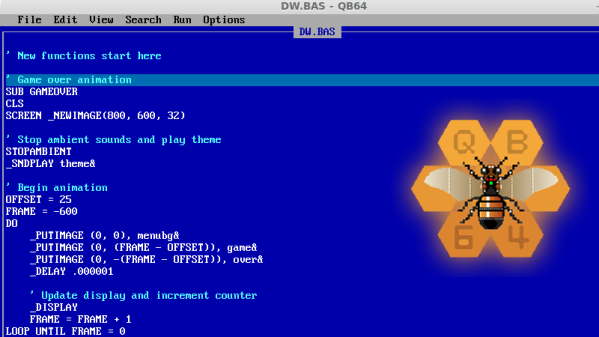
When I got my first computer, a second hand 386 running MS-DOS 6.22, I didn’t have an Internet connection. But I did have QuickBASIC installed and a stack of programming magazines the local library was throwing out, so I had plenty to keep myself busy. At the time, I thought QuickBASIC was more or less indistinguishable from magic. I could write simple code and compile it into an .exe, put it on a floppy, and give it to somebody else to run on their own machine. It seemed too good to be true, how could this technology possibly be improved upon?
 Of course, that was many years ago, and things are very different now. The programming languages du jour are worlds more capable than the plodding BASIC variants of the 80’s and 90’s. But still, when I found a floppy full of programs I wrote decades ago, I couldn’t help but wonder about getting them running again. With something like DOSBox I reasoned I should be able to install the QuickBASIC IDE and run them like I was back on my trusty 386.
Unfortunately, that was not to be. Maybe I’m just not well versed enough in DOSBox, but I couldn’t get the IDE to actually run any of the source code I pulled off the floppy. This was disappointing, but then it occured to me that modern BASIC interpreters are probably being developed in some corner of the Internet, and perhaps I could find a way to run my nearly 30 year old code without having to rely on 30 year old software to do it. Continue reading “QuickBASIC Lives On With QB64”

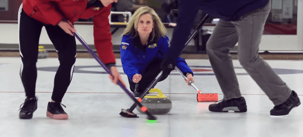
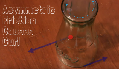 If you’ve been watching the Olympics, you’ve probably seen some curling, the Scottish sport of competitively pushing stones on ice. As the name implies, curling stones don’t go straight. The thrower pushes them with a bit of rotation, and the stones curve in the direction they are rotating. This is exactly the opposite of what one would expect — try it yourself with an inverted drinking glass on a smooth table. The glass will curl opposite the direction of rotation. Clockwise spin will result in a curl to the left, counterclockwise in a curl to the right.