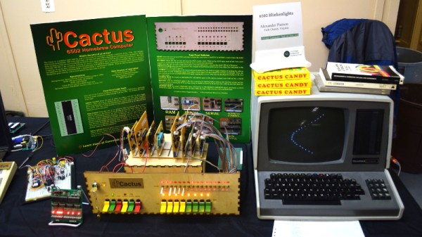
Among the rows of digital dinosaurs, one blinking front panel stood out. It certainly looked the part of a retro computer; with banks of blinking LEDs and multicolored paddle switches. But upon closer inspection, the laser cut wooden front panel betrays the fact that this machine is an impostor. It may have the appearance of a machine from the heady days where home computers looked like they could have doubled as a prop on the bridge of Kirk’s Enterprise, but it’s actually a product of much more modern provenance.
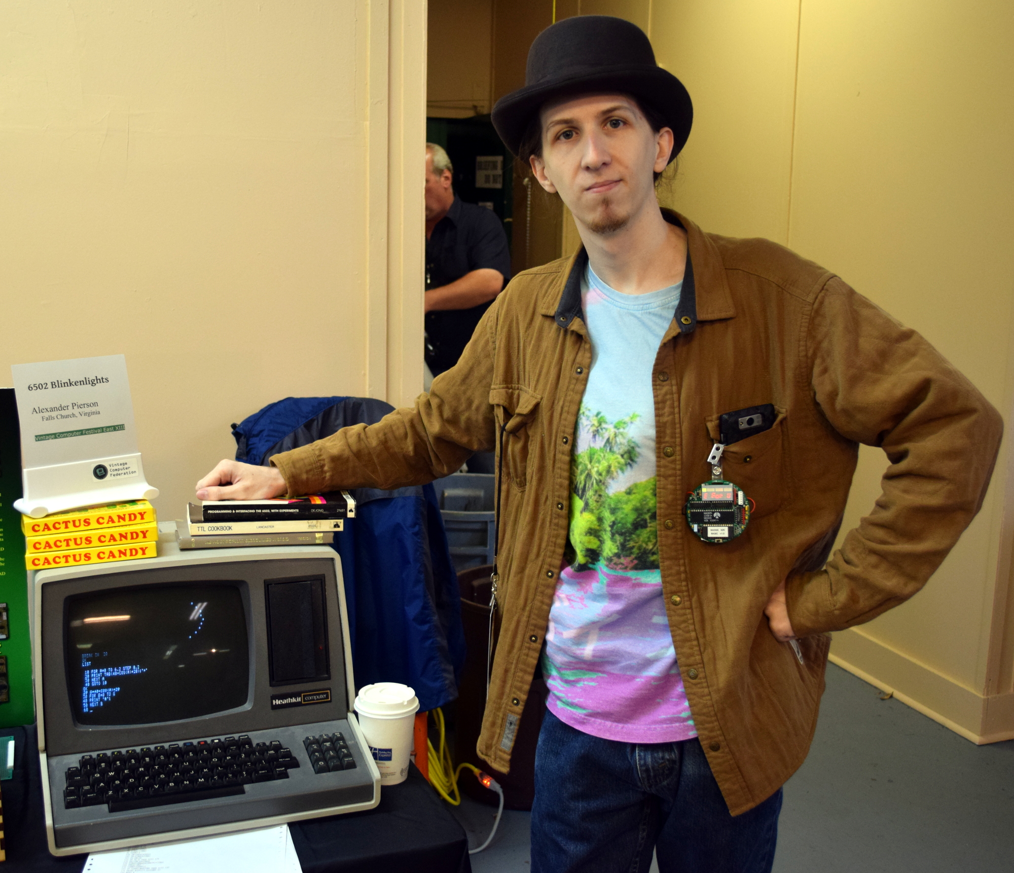 It’s called the Cactus, a love letter to the homebrew microcomputers of the 1970’s, designed and built by somebody at least 20 years too young to have experienced them the first time around. Alexander Pierson created the Cactus not because he had fond memories of putting together an Altair 8800 in 1975, but because he’s fascinated with the retro computer experience: the look of the front panel, the satisfying clunk of era-appropriate switches, and the idea that the computer’s inner workings aren’t an abstract black box but rather something you can interact with and study. Judging by all the attention the Cactus got at VCF East XIII, he’s not the only one.
Let’s take a look at everything Alexander poured into this retrocomputer build.
Continue reading “VCF East 2018: Cactus, Retro Because It Wants To Be”