When you live in a totalitarian, controlled and “happy” society, and you want to be a hacker, you have to hack the social system first. Being just an engineer doesn’t cut it, you have to be a hypocrite, dissident and a smuggler at the same time. That’s the motto of my personal story, which starts in Yugoslavia, and ends in Serbia. No, I didn’t move, I’m still in Belgrade, only the political borders have changed.
Half a century ago, when I was in elementary school, I discovered the magical world of HAM radio. I became a member of two amateur radio clubs, passed all exams and got my licence and callsign, which was YU1OPC. I was delighted, but after five years, the party was over. What happened? Well, one day the police paid a visit to all registered owners of CB Band equipment and simply took that equipment away. No one knows why they did it, but it was probably off the books, as we never got any written confirmation, and no one ever saw their equipment again.
Procrastination is a wonderful thing, but now is the time to stop delaying. Get those hacks documented and entered in the 2015 Hackaday Prize. We’ll close entries in just about two weeks. There’s a handy little countdown on the Prize page which lets you know that your entry must be in by August 17th at 1:50pm PDT (UTC-7).
There’s a lot at stake here, so let’s take another look at what this is all about: Build something that solves a problem faced by a lot of people and you could score a Trip to Space, $100,000 for Best Product, or 2nd-5th place prizes worth $5,000-10,000 each.
Of course the goal is to show off your build. This could end up inspiring others to Build Something that Matters and that means to win you need to document your work. Join us after the break to see the minimum needed for your entry to qualify for judging.
In a perfect futuristic world you have pre-emptive 3D scans of your specific anatomy. They’d be useful to compare changes in your body over time, and to have a pristine blueprint to aid in the event of a catastrophe. As with all futuristic worlds there are some problems with actually getting there. The risks may outweigh the rewards, and cost is an issue, but having 3D imaging of a sick body’s anatomy does have some real benefits. Take a journey with me down the rabbit hole of 3D technology and Gray’s Anatomy.
In March of 2014, I knew my eight year old daughter was sick. Once borderline overweight, she was now skeletally thin and fading away from us. A pre-dawn ambulance ride to the hospital gave us the devastating news – our daughter had Type 1 diabetes, and would be dependent on insulin injections for the rest of her life.
This news hit me particularly hard. I’ve always been a preparedness-minded kind of guy, and I’ve worked to free myself and my family from as many of the systems of support as possible. As I sat in the dark of the Pediatric ICU watching my daughter slowly come back to us, I contemplated how tied to the medical system I had just become. She was going to need a constant supply of expensive insulin, doled out by a medical insurance system that doesn’t understand that a 90-day supply of life-saving medicine is a joke to a guy who stocks a year supply of toilet paper. Plus I had recently read an apocalyptic novel where a father watches his 12-year old diabetic daughter slip into a coma as the last of her now-unobtainable insulin went bad in an off-grid world. I swore to myself that I’d never let this happen, and set about trying to find ways to make my own insulin, just in case.
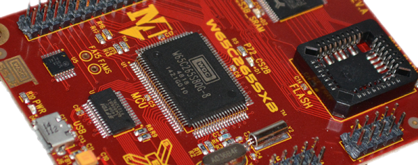
The 6502 is a classic piece of computing history. Versions of this CPU were found in everything from the Apple ][, to the Nintendo Entertainment System, and the Commodore 64. The history of the 6502 doesn’t end with video games; for the last forty years, this CPU has found its way into industrial equipment, medical devices, and everything else that doesn’t need to be redesigned every two years. Combine the longevity of the 6502 with the fact an entire generation of developers first cut their teeth on 6502 assembly, and you have the makings of a classic microprocessor that will, I’m sure, still be relevant in another forty years.
The folks at WDC recently contacted me to see if I would give their hardware a close look, and after providing a few boards, this hardware proved to be both excellent. They’re great for educators adventurous enough to deviate from the Arduino, Processing, and Fritzing zeitgeist, and for anyone who wants to dip their toes into the world of 65xx development.
I’m not getting any younger, in fact I’m getting older by the day. This fact along with the fact that this year is the 30th anniversary of the Commodore C-128 and the original Commodore Amiga prompted me to attend this year’s CommVEx in Las Vegas lest I not be around for the next significant anniversary. For those that don’t know me, I designed the C-128 at the ripe old age of 25 back in 1984-85, though I would ask that you not hold that against me as it was a very long time ago.
Also this year Dr. Leonard Tramiel, son of Commodore’s founder Jack Tramiel, was able to swing by which was an unprecedented and unforgettable event.
There comes a time when you need to wire up three, four, or more identical i2c devices to a common microcontroller. Maybe you’re thinking about driving 128 seven-segment displays with eight of those MAX6955 16-way digit drivers, or maybe you have a robot full of joints–each of which needs a BNO055 inertial sensor for angle estimation. (See above.) Crikey! In both of those cases, you’re best bet might be a schnazzy I²C device that can do most of the work for you. The problem? With a single I²C bus, there’s no standard way defined in the protocol for connecting two or more devices with the same address. Shoot! It would’ve been handy to wire up three BNO055 IMUs or eight MAX6955s and call it a day. Luckily, there’s a workaround.
We’ve seen some clever tricks in the past for solving this problem. [Marv G‘s] method involves toggling between a device’s default and alternate address with an external pin. This method, while clever, assumes that the device (a) has an alternate I²C address and (b) features an external pin for toggling that address.
I’ll introduce two additional methods for getting the conversation started between your micro’ and your suite of identical sensors. The first is “a neat trick,” but somewhat impractical for widespread use. The second is far more production-worthy–something you could gloat over and show off to your boss! Without further ado, let’s get started with Method 1.
Lastly, if you’d like to follow along, feel free to check out the source code on Github.
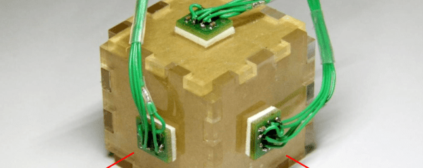
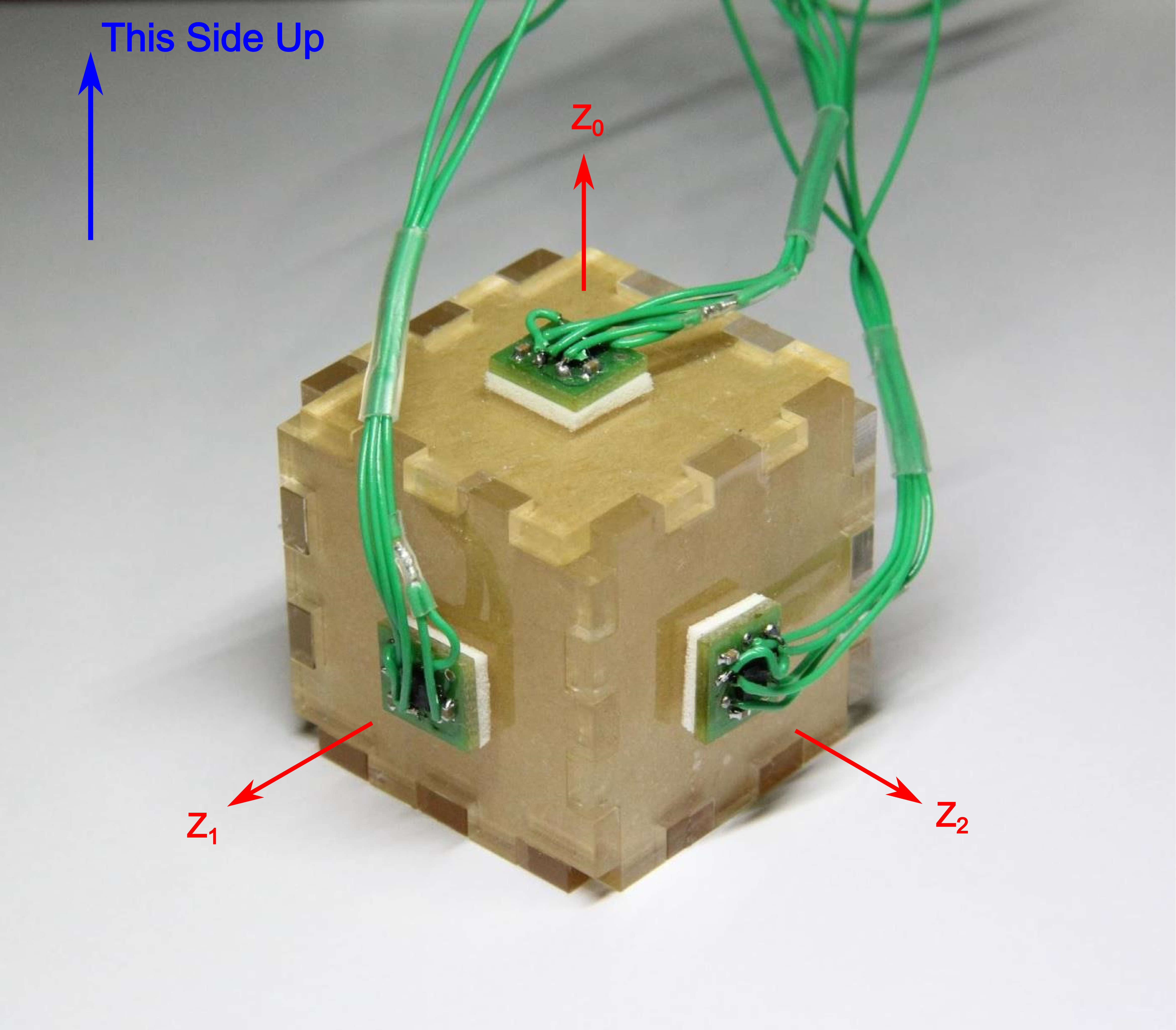
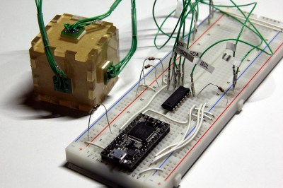
In both methods, I’m using the same sensor setup to check that each circuit behaves correctly. I happened to have a bunch of extra BMA180s on the bench, so I rolled out an example based on these chips. Back in the day, the BMA180 was a pretty common three-axis digital accelerometer. It has an I²C interface with two optional addresses. For the purpose of this example, I’m fixing them all with the same address. I’ve mounted three of these guys on mutually perpendicular axes of my acrylic “test cube,” and I’m reading each chip’s Z-axis. In this configuration I can easily pick out the gravity vector from the corresponding sensor as the data goes flying by my serial port window. If I can uniquely address each sensor and read the data, I’ve got a working circuit.
Method 1: Splicing Clocks into Chip-Selects
This method tips its hat towards SPI in that it behaves in an oddly similar fashion. If you’re feeling rusty on SPI, here’s a quick recap.
A Quick SPI Refreshment:
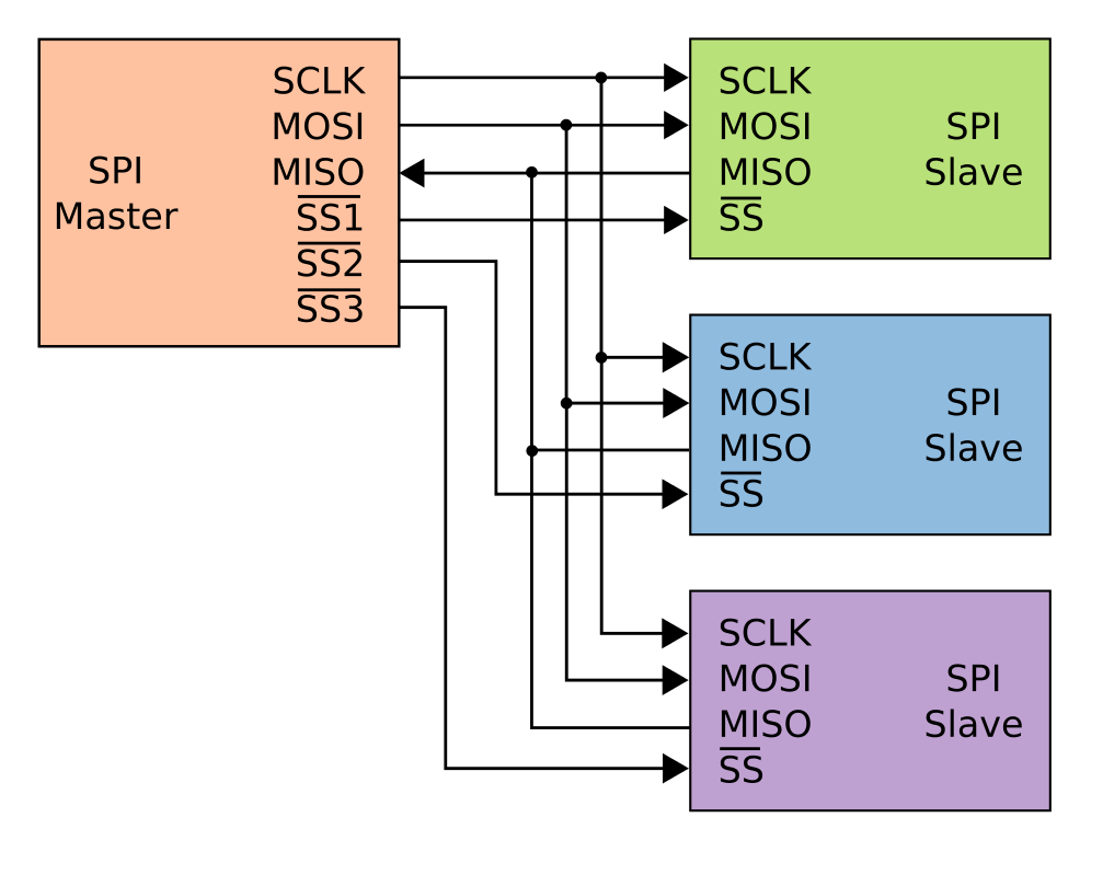
SPI, like I²C, is another protocol that shares both its clock and data lines with multiple slave devices. The difference, though, lies in the addressing scheme to talk to these devices that share the same bus. With SPI, while clock and data lines are shared, devices are addressed with separate chip-select (CS) lines.
The master microcontroller dedicates a unique output pin to each device (~SS1, ~SS2, and ~SS3 in this illustration). When the master micro’ wants to talk to a device, it asserts that device’s chip-select input pin by pulling it to logic LOW, and the conversation begins over the data bus. With the chip select LOW, the corresponding slave listens to the data on the bus. Meanwhile, all other devices ignore the conversation between the master and it’s chosen slave by keeping their bus pins in a high impedance state.
Giving I²C Its Own Chip-Selects:
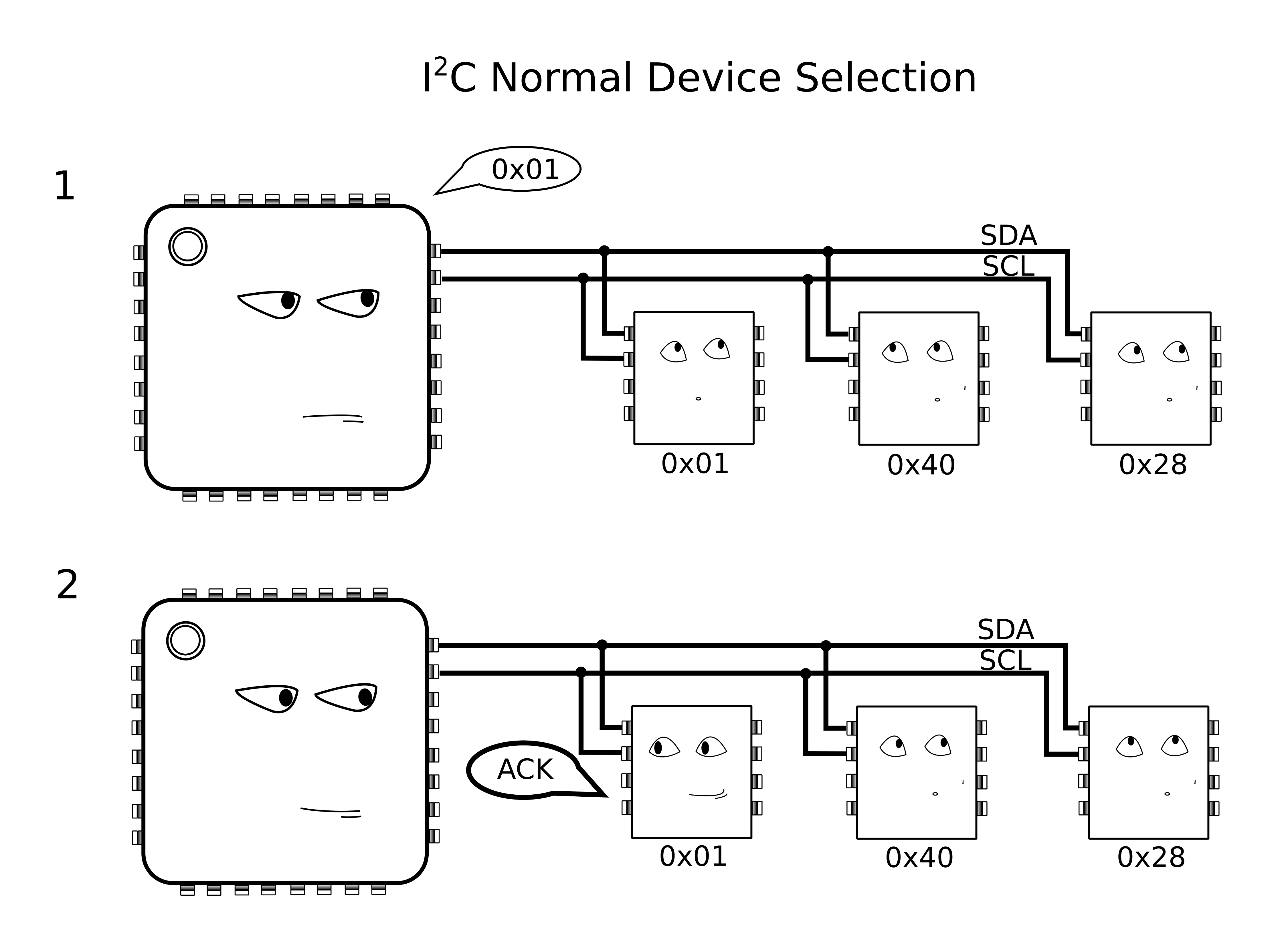
With I²C, Clock (SCL) and Data (SDA) lines are still shared between all I2C slave devices, but the addressing scheme happens by sending a message heard by all devices on the bus. To single out one device on the shared bus, the master first passes down the address of the slave device it wants to talk to, after which that slave replies with an ACKnowledge, and all other slaves ignore the data that follows until both data transmission is complete and the bus is “released.”
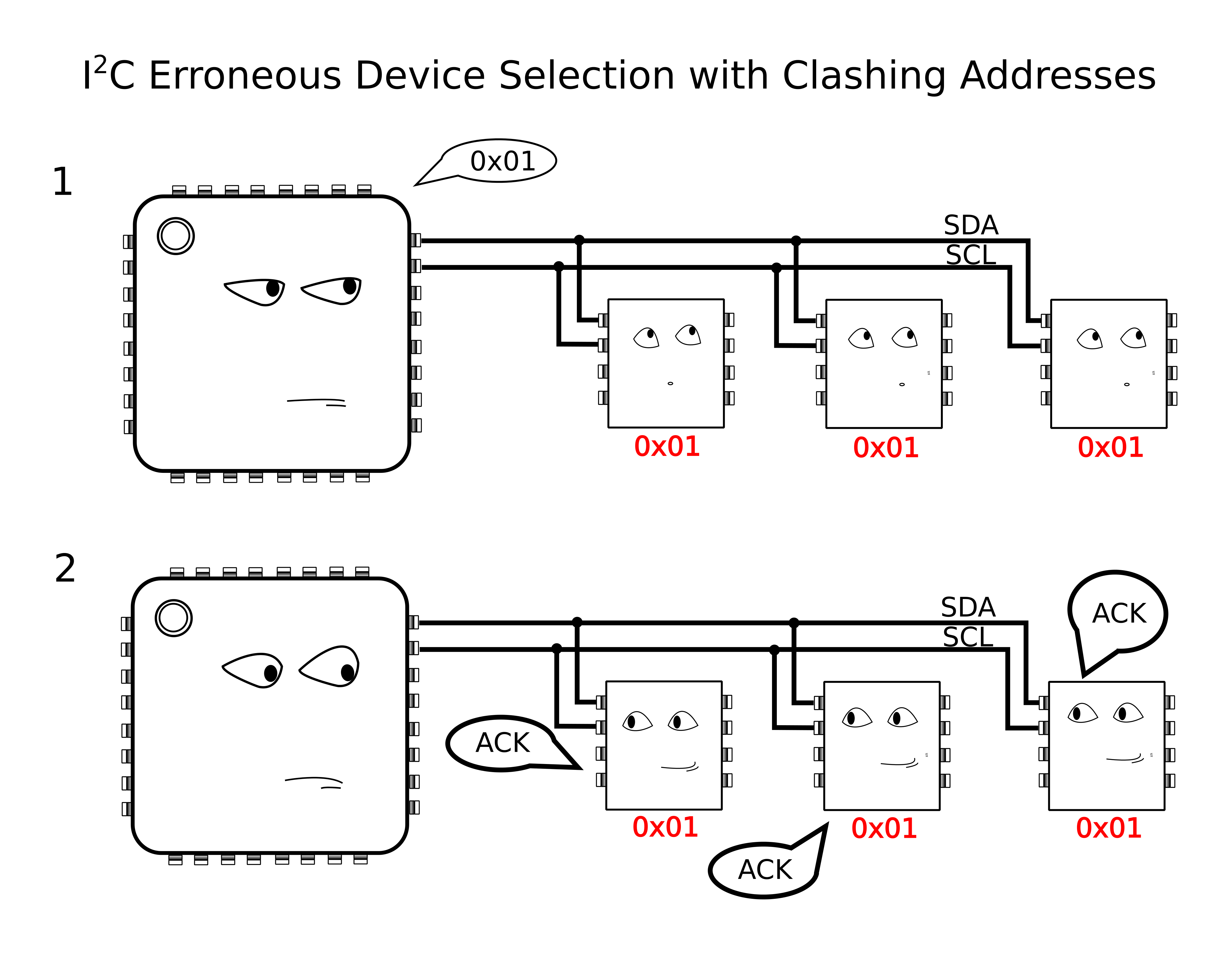
Because we have the problem of multiple devices with shared addresses, in theory, all of these devices would reply when the master passes down their shared address, and there’s no way for the master to single out a single device. In reality, this behavior is undefined on the I²C protocol.
Yikes! Anything goes when we wander away from defined behavior, so we try to avoid these things in practice.
The solution?
According to the I²C spec, It just so happens that an I²C slave device will ignore changes on the data line (SDA) provided that the clock line (SCL) is held high. In this method, I’ll “split” the SCL line into multiple SCL lines such that each shared I²C device gets its own SCL. By selectively rerouting the clock to each I²C device one-at-a-time, I’ve essentially turned the SCL line into a “chip select.”
To chop up that clock line, I’ll need a demultiplexer. A demultiplexer (or decoder) takes a logical input and reroutes it to one of several outputs based on the binary select lines.
I’ve dropped in the 74AC11138 eight-way demultiplexer for this task. It’s fast, capable of switching at megahertz rates, and its outputs default to logic HIGH. That second note is handy since idle SCL lines also default to logic HIGH.
The setup is shown in a simplified schematic above. In it, I’m using a Teensy 3.0 posing as the I²C bus master. To the right of the Teensy is the collection of identical chips, BMA180 accelerometers in this case. In the middle is the 74AC11138 eight-way demultiplexer.
Cons of this Method:
There’s a minor drawback with this technique, though, in that it doesn’t support I²C’s clock-stretching feature. Taking a step back, this method assumes that the SCL line is inherently unidirectional, controlled by only the I²C bus master. In other words, we’re making the assumption that data on the SCL line is only sent from master to slave and never the other way around. If your I²C slave devices implement clock-stretching, however, this assumption breaks down.
What is Clock Stretching?
Clock stretching is a method defined by the I²C protocol where the chip needs to “buy itself more time” and holds the SCL line low, hence, signalling to the master that it’s not ready for the upcoming data. In this scenario, the slave actively controls the SCL line, and it happens to be the only case where data moves up the SCL line from slave to master. In a setup with our demultiplexer between the master and our set of identical slaves, these slaves won’t be able to send back the clock-stretching signal to the master to indicate that they aren’t ready for data, if they happen to implement clock stretching. That said, clock stretching is a pretty rare feature among I²C-compatible devices, so this method is likely to work among a number of chips out now.
More Next Week
That’s all for Method 1. Thanks for tuning in, and check back next week for a slightly-more-professional method of tackling this same problem.








 I’ve dropped in the 74AC11138 eight-way demultiplexer for this task. It’s fast, capable of switching at megahertz rates, and its outputs default to logic HIGH. That second note is handy since idle SCL lines also default to logic HIGH.








