Immersive VR With A 200-Degree Stereoscopic Camera

VR is in vogue, but getting on board requires a steep upfront cost. Hackaday.io user [Colin Pate] felt that $800 was a bit much for even the cheapest commercial 360-degree 3D camera, so he thought: ‘why not make my own for half that price?’

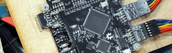
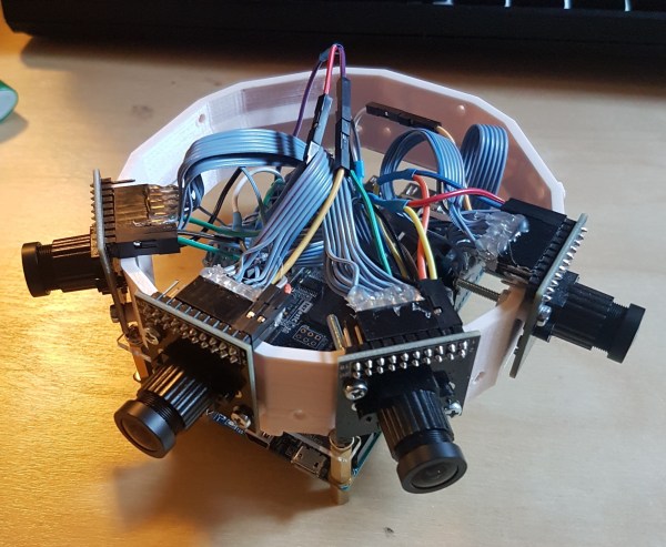
[Pate] knew he’d need a lot of bandwidth and many GPIO ports for the camera array, so he searched out the Altera Cyclone V SOC FPGA and a Terasic DE10-Nano development board to host it. At present, he has four Uctronics OV5642 cameras on his rig, chosen for their extensive documentation and support. The camera mount itself is a 3D-printed octagon so eight of the OC5642 can capture a full 360-degree photo.

Next: producing an image!

Continue reading “Immersive VR With A 200-Degree Stereoscopic Camera”

FPGA Metastability Solutions

Gisselquist Technology recently posted a good blog article about metastability and common solutions. If you are trying to learn FPGAs, you’ll want to read it. If you know a lot about FPGAs already, you might still pick up some interesting tidbits in the post.

Don’t let the word metastability scare you. It is just a fancy way of saying that a flip flop can go crazy if the inputs are not stable for a certain amount of time before the clock edge and remain stable for a certain amount of time after the clock edge. These times are the setup and hold times, respectively.

Normally, your design tool will warn you about possible problems if you are using a single clock. However, any time your design generates a signal with one clock and then uses it somewhere with another clock, metastability is a possible problem. Even if you only have one clock, any inputs from the outside world that don’t reference your clock — or, perhaps, any clock at all — introduce the possibility of metastability. Continue reading “FPGA Metastability Solutions”

FPGA Design From Top To Bottom

[Roland Lutz] gave a talk about FPGA design using the free tools for Lattice devices at the MetaRheinMainChaosDays conference this year. You can see the video below. It’s a great introduction to FPGAs that covers both the lowest-level detail and some higher level insight. If you’re getting started with these FPGAs, this video is a must-see.

[Roland] starts with the obligatory introductory material. He then jumps into an actual example before zooming back out to look at the internal details of the Lattice FPGA. For instance, this FPGA supports multiple bitstreams, so you can switch between different “programs” on the fly.

Continue reading “FPGA Design From Top To Bottom”

Hackaday Prize Entry: Programming FPGAs With Themselves

It’s been a few years since the introduction of the first Open Source toolchain for FPGAs. You would think a free and Open way to program FPGAs would be a boon for hardware development, but so far we’re really not seeing much in the way of a small, cheap, clever device that brings FPGAs to the masses.

We don’t know if [Luke]’s entry to the Hackaday Prize is the killer project that will do it, but it is very neat. He’s designed a tiny FPGA development board using a Lattice iCE40 FPGA that’s able to program itself over USB. It’s small, it’s cheap, it’s easy to use, and there are working examples of FPGA development using this board.

If you’re thinking this tiny little board looks familiar, you’re right. [Luke] has been working on a similar board, the A-Series, but this latest version has a USB port instead of pins for a JTAG adapter. This USB functionality is pretty clever — instead of using a seperate microcontroller, [Luke] is using the FPGA itself to reprogram the user configuration into a Flash chip. Once that’s up and running, the bootloader is removed and doesn’t consume any FPGA resources.

[Luke] is also working on an amazing hobbyist guide to FPGAs that leans heavily on the Open Source toolchain available for these Lattice FPGAs and his board. That’s a huge benefit to the community, and an excellent entry to the Hackaday Prize.

Homemade 6 GHz Radar, V3

The third version of [Henrik Forstén] 6 GHz frequency-modulated continuous wave (FMCW) radar is online and looks pretty awesome. A FMCW radar is a type of radar that works by transmitting a chirp which frequency changes linearly with time. Simple continuous wave (CW) radar devices without frequency modulation cannot determine target range because they lack the timing mark necessary for accurately time the transmit and receive cycle in order to convert this information to range. Having a transmission signal modulated in frequency allows for the radar to have both a very high accuracy of range and also to measure simultaneously the target range and its relative velocity.

Like the previous versions, [Henrik] designed a four-layer pcb board and used his own reflow oven to solder all the ~350 components. This process, by itself, is a huge accomplishment. The board, much bigger than the previous versions, now include digital signal processing via FPGA.

[Henrik’s] radar odyssey actually started back in 2014, where his first version of the radar was detailed and shared in his blog. A year later he managed to solve some of the issues he had, design a new board with significant improvements and published it again. As the very impressive version three is out, we wonder what version four will look like.

In the video of [Henrik] riding a bicycle in a circle in front of the radar, we can see the static light posts and trees while he, seen as a small blob, roams around:

Continue reading “Homemade 6 GHz Radar, V3”

Apple II FPGA

[Stephen Edwards] had some time one Christmas. So he took a DE2 FPGA board and using VHDL built a pretty faithful reproduction of an Apple II+ computer. He took advantage of VHDL modules for the 6502 CPU and PS/2 keyboard, and focused more on the video hardware and disk emulation.

According to [Stephen], you can think of the Apple II as a video display that happens to have a computer in it. The master clock is a multiple of the color burst frequency, and the timing was all geared around video generation. [Stephen’s] implementation mimics the timing, although using more modern FPGA-appropriate methods.

Continue reading “Apple II FPGA”

Learn FPGA Programming From The 1940s

We often think that not enough people are building things with FPGAs. We also love the retrotechtacular posts on old computer hardware. So it was hard to pass up [karlwoodward’s] post about the Chip Hack EDSAC Challenge — part of the 2017 Wuthering Bytes festival.

You might recognize EDSAC as what was arguably the first operational computer if you define a computer as what we think of today as a computer. [Maurice Wilkes] and his team invented a lot of things we take for granted today including subroutines (Wheeler jumps named after a graduate student).

The point to the EDSAC challenge was to expose people to creating designs with FPGAs, particularly using the Verilog hardware description language (HDL). If you want to follow along or run your own Chip Hack, the materials are available on the Web. You can see an FPGA driving a tape punch to create souvenir tapes in the video, below.

Some of the exercises are pretty simple and that’s perfect if you are starting out. The challenge uses a board with a Lattice ice40 FPGA and the open source toolchain for Lattice we’ve covered before. In fact, we’ve even done our own tutorials on the same basic device (but not the same board). Our final project generated PWM, not paper tape.

For the record, EDSAC was awesome. The execution unit was serial and processed bits that marched in one at a time over a mercury delay line. There is quite a bit of documentation and even some simulators, so if you ever wanted to get your hands into an old computer, this one isn’t a bad one to try.

Continue reading “Learn FPGA Programming From The 1940s”