Printed circuit boards have never been cheaper or easier to make. We’re not that far removed from a time where, if you wanted a printed circuit board, your best and cheapest option would be to download some proprietary software from a board house, use their terrible tool, and send your board off to be manufactured. A few copies of a 5x5cm board would cost $200. Now, anyone can use free (as in beer, if not speech) software, whip up a board, and get a beautifully printed circuit board for five dollars. It has never been easier to make a printed circuit board, and with that comes a new medium of artistic expression. Now, we can make art on PCBs.
PCB as Art
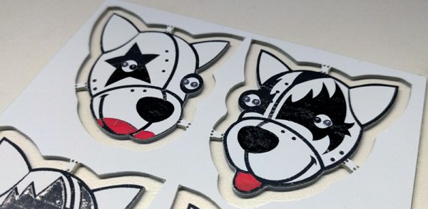
For the last year or so, Hackaday has been doing a deep-dive into the state of artistic PCBs. By far our biggest triumph is the Tindie Blinky Badge, an artistic representation of a robot dog with blinking LED eyes. [Andrew Sowa] turned some idiot into PCB coinage, and that same idiot experimented with multicolor silkscreen at last year’s DEF CON.
Others have far surpassed anything we could ever come up with ourselves; [Trammel Hudson] created an amazing blinky board using the standard OSHPark colors, and [Blake Ramsdell] is crafting full panels of PCB art. The work of Boldport and [Saar Drimer] has been featured in Marie Claire. The world of art on printed circuit boards has never been more alive, there has never been more potential, and the artistic output of the community is, simply, amazing. We are witnessing the evolution of a new artistic medium.
Printed circuit boards are a limited medium. Unless you want to shell out big bucks for more colors of silkscreen, weird colors of soldermask, or even multiple colors of soldermask, you will be limited to the standard stackup found in every board house. One color, the fiberglass substrate, will be a pale yellow. The copper layer will be silver or gold, depending on the finish. The soldermask will be green, red, yellow, blue, black, white, and of course purple if you go through OSH Park. The silkscreen will be white (or black if you go with a white soldermask). What I’m getting at is that the palette of colors available for PCB art is limited… or at least it has been.
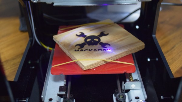
For a few months now, Hackaday has been experimenting with a new process for adding colors to printed circuit boards. This is a manufacturing process that translates well into mass production. This is a process that could, theoretically, add dozens of colors to any small PCB. It’s just an experiment right now, but we’re happy to report some limited success. It’s now easy — and cheap — to add small amounts of color to any printed circuit board.
Continue reading “Successful Experiments In Multicolor Circuit Boards” →
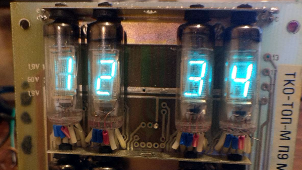
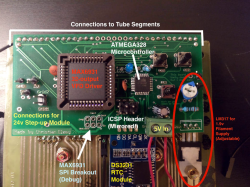 After getting the VFDs lighting up and figuring out the circuitry on the back, [InThePartsBin] decided that a clock was the best thing to build out of it. It was decided that a specialized VFD driver chip was the easiest way to make the thing work, so a MAX6934 was ordered. To give the clock some brains, an ATmega328 was recruited and to keep time, [InThePartsBin] had some DS3231 real-time clock modules left over from a previous project, so they were recruited as well. A daughterboard was designed to sit on the back of the vintage board and hold the ‘328 and the VFD driver chip.