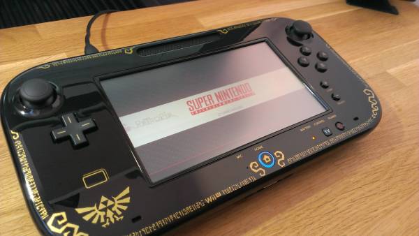
When a consumer electronics device is sold in the US, especially if it has a wireless aspect, it must be tested for compliance with FCC regulations and the test results filed with the FCC (see preparing your product for FCC testing). These documents are then made available online for all to see in the Office of Engineering and Technology (OET) Laboratory Equipment Authorization System (EAS). In fact, it’s this publishing in this and other FCC databases that has led to many leaks about new product releases, some of which we’ve covered, and others we’ve been privileged enough to know about before the filings but whose breaking was forced when the documents were filed, like the Raspberry Pi 3. It turns out that there are a lot of useful things that can be accomplished by poring over FCC filings, and we’ll explore some of them.
hardware1803 Articles
A Completely Open Microcontroller

We don’t know about you, but the idea of an Arduino-class microprocessor board which uses completely open silicon is a pretty attractive prospect to us. That’s exactly [onchipUIS]’s stated goal. They’re part of a research group at the Universidad Industrial de Santander and have designed and taped out a RISCV implementation with Cortex M0-like characteristics.
The RISCV project has developed an open ISA (instruction set architecture) for modern 32-bit CPUs. More than 40 research groups and companies have now jumped on the project and are putting implementations together.
[onchipUIS] is one such project. And their twitter timeline shows the rapid progress they’ve been making recently.

After tapeout, they started experimenting with their new wirebonding machine. Wirebonding, particularly manual bonding, on a novel platform is a process fraught with problems. Not only have [onchipUIS] successfully bonded their chip, but they’ve done so using a chip on board process where the die is directly bonded to a PCB. They used OSHPark boards and described the process on Twitter.
The board they’ve built breaks out all the chip’s peripherals, and is a convenient test setup to help them validate the platform. Check it, and some high resolution die images, out below. They’re also sending us a die to image using our electron microscope down at hackerfarm, and we look forward to the results!
Wireless Trivia Game Buzzers Using HopeRF RFM69
TV game shows follow a formula that hasn’t changed much in sixty years. The celebrity presenter, the glamorous assistant, the catch phrases, the gaudy plywood sets, the nervous contestants, and of course the buzzers.
If you want to do a trivia quiz of your own it’s easy enough to dispense with presenter, assistant, set, and catch phrase, but as well as the contestants you’ll still need the buzzers. You can make a mess of wires that the TV technicians of old would have concealed within that set, but in your home or at the pub that could rapidly become inconvenient.
[Larry] solved his trivia game buzzer problems by building a wireless buzzer set. It features 3D printed enclosures containing Adafruit Feather microcontrollers, and instead of wires it uses RFM69 900MHz radio modules. The master unit displays the quickest contestant on an OLED screen, it features a low power standby mode between button presses to save battery power, and care has been taken to add a random timing to button presses to try to avoid collisions.
The buttons themselves started with a 3D printed button working a single tactile switch, but moved to a set of three switches in a triangle after edge presses failed to activate the single switch.
We’ve featured a wired game show buzzer before, but for the complete game show experience how about this countdown timer?
Hackaday Prize Entry: Vendotron
A recurring idea in hackspaces worldwide seems to be that of the vending machine for parts. Need An Arduino, an ESP8266, or a motor controller? No problem, just buy one from the machine!
Most such machines are surplus from the food and drink vending industry, so it’s not unusual to be able to buy an Arduino from a machine emblazoned with the logo of a popular chocolate bar. These machines can, however, be expensive to buy second-hand, and will normally require some work to bring into operation.
A vending machine is not inherently a complex machine nor is it difficult to build when you have the resources of a hackspace behind you. [Mike Machado] is doing just that, building the Vendotron, a carousel vending machine constructed from laser cut plywood and MDF. The whole thing is controlled by an Arduino, with the carousel belt-driven from a stepper motor.
It’s not doing anything commercial vending machines haven’t been doing for years, except maybe having a software interface that allows phone and Bitcoin payments. Where this project scores though is in showing that a vending machine need not be expensive or difficult to build, and broadening access to them for any hackspace that wants one.
We’ve had a few vending machines here before, like this feature on the prototyping process for commercial machines, or even this one that Tweets. Sadly few have a secret button to deliver a free soda though.
Choosing A ‘Scope: Examining Bandwidth
A few weeks ago I asked the Hackaday community for some help and advice in buying a new budget oscilloscope. Thank you very much to those of you who responded both here online and in person among my friends closer to home. I followed the overwhelming trend in the advice I received, and bought myself a Rigol DS1054z, an instrument with which I am very happy. It’s a nominally a 50 MHz scope, but there’s a software hack that can bring it up to 100 MHz. How fast can it go?

This question became a mini scope-shootout after a conversation with my Hackaday colleague [Elliot] about measuring oscilloscope bandwidth, and then my fellow Oxford Hackspace members producing more than one scope for comparison. You know who you are, thank you. I found myself with ready access to several roughly equivalent models and one very high-end one in specification terms representing different strata of test equipment manufacture, and with the means to examine their performance.
Taking A U2F Hardware Key From Design To Production
Building a circuit from prototyping to printed circuit board assembly is within the reach of pretty much anyone with the will to get the job done. If that turns out to be something that everyone else wants, though, the job gets suddenly much more complex. This is what happened to [Conor], who started with an idea to create two-factor authentication tokens and ended up manufacturing an selling them on Amazon. He documented his trials and tribulations along the way, it’s both an interesting and perhaps cautionary tale.
[Conor]’s tokens themselves are interesting in their simplicity: they use an Atmel ATECC508A specifically designed for P-256 signatures and keys, a the cheapest USB-enabled microcontroller he could find: a Silicon Labs EFM8UB1. His original idea was to solder all of the tokens over the course of one night, which is of course overly optimistic. Instead, he had the tokens fabricated and assembled before being shipped to him for programming.
Normally the programming step would be straightforward, but using identical pieces of software for every token would compromise their security. He wrote a script based on the Atmel chip and creates a unique attestation certificate for each one. He was able to cut a significant amount of time off of the programming step by using the computed values with a programming jig he built to flash three units concurrently. This follows the same testing and programming path that [Bob Baddeley] advocated for in his Tools of the Trade series.
From there [Conor] just needed to get set up with Amazon. This was a process worthy of its own novel, with Amazon requiring an interesting amount of paperwork from [Conor] before he was able to proceed. Then there was an issue of an import tariff, but all-in-all everything seems to have gone pretty smoothly.
Creating a product from scratch like this can be an involved process. In this case it sounds like [Conor] extracted value from having gone through the entire process himself. But he also talks about a best-case-scenario margin of about 43%. That’s a tough bottom line but a good lesson anyone looking at building low-cost electronics.
Hackaday Prize Entry: Raspberry Pi Thermal Imaging
High up on the list of desirable technologies that are edging into the realm of the affordable for the experimenter is the thermal camera. Once the exclusive preserve of those with huge budgets, over the last few years we’ve seen the emergence of cameras that are more affordable, and most recently a selection of thermal camera modules that are definitely within the experimenter’s range. They may not yet have high resolution, but they are a huge improvement on nothing, and they are starting to appear in projects featured on sites like this one.
One such device is the Melexis MLX90621, a 16×4 pixel thermal sensor array in a TO39 can with an I2C interface. It’s hardly an impulse purchase in single quantities and nor is it necessarily the cheapest module available, but its price is low enough for [Alpha Charlie] to experiment with interfacing it to a Raspberry Pi for adding a thermal camera overlay to the pictures from its visible light camera.
The wiring for the module is simplicity itself, and he’s created a couple of pieces of software for it that are available on his GitHub repository. mlxd is a driver daemon for the module, and mixview.py is a Python graphical overlay script that places the thermal array output over the camera output. A run-through of the device and its results can be seen in the video below the break.
Continue reading “Hackaday Prize Entry: Raspberry Pi Thermal Imaging”


