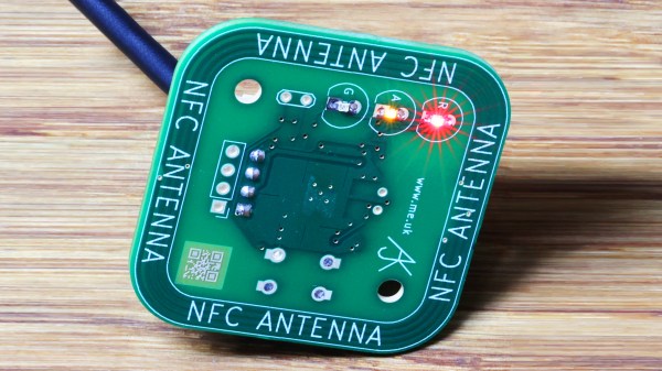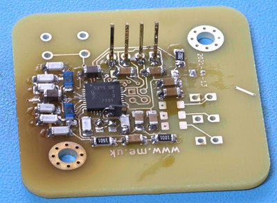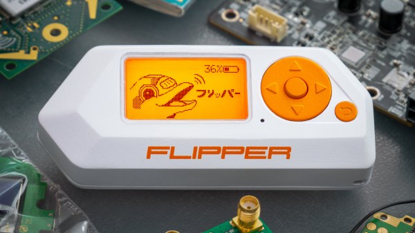
Flipper Zero is an open-source multitool for hackers, and [Pavel] recently shared details on what goes into the production and testing of these devices. Each unit contains four separate PCBs, and in high-volume production it is inevitable that some boards are faulty in some way. Not all faults are identical — some are not even obvious — but they all must be dealt with before they end up in a finished product.
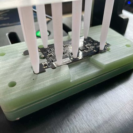
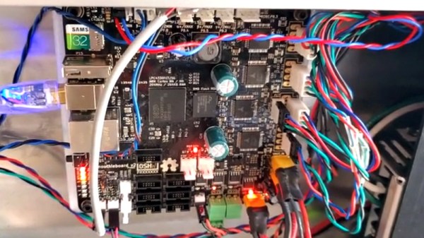
Designing a process to effectively detect and deal with faults is a serious undertaking, one the Flipper Zero team addressed by designing a separate test station for each of the separate PCBs, allowing detection of defects as early as possible. Each board gets fitted into a custom test jig, then is subjected to an automated barrage of tests to ensure everything is as expected before being given the green light. A final test station gives a check to completed assemblies, and every test is logged into a database.
It may seem tempting to skip testing the individual boards and instead just do a single comprehensive test on finished units, but when dealing with production errors, it’s important to detect issues as early in the workflow as possible. The later a problem is detected, the more difficult and expensive it is to address. The worst possible outcome is to put a defective unit into a customer’s hands, where a issue is found only after all of the time and cost of assembly and shipping has already been spent. Another reason to detect issues early is that some faults become more difficult to address the later they are discovered. For example, a dim LED or poor antenna performance is much harder to troubleshoot when detected in a completely assembled unit, because the fault could be anywhere.
[Pavel] provides plenty of pictures and details about the production of Flipper Zero, and it’s nice to see how the project is progressing since its hyper-successful crowdfunding campaign.
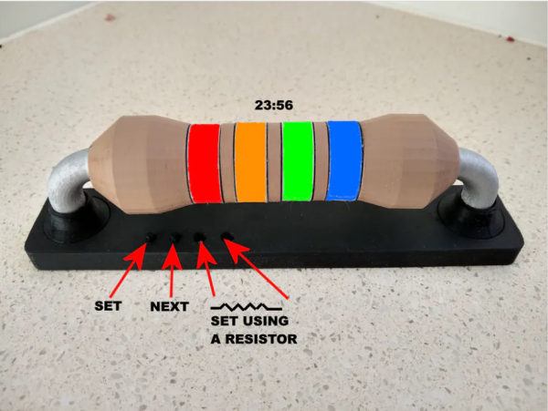
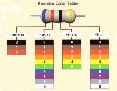 Each of the four bands represents a digit in the standard HH:MM representation of time, and for anybody well-versed in resistor codes this is sure to be a breeze to read. The clock itself was designed by [John Bradnam]. It’s body is 3D printed, with RGB LEDs to brightly illuminate each segment. The whole thing is controlled by an old favorite – an ATtiny, supported by a Real Time Clock (RTC) chip for accurate timekeeping.