FCC Filing Reveals Tasty Hardware McSecrets

If you’ve visited a McDonald’s recently, you might have noticed something of a tonal shift. Rather than relying on angsty human teenagers to take customer orders, an increasing number of McDonald’s locations are now using self-serve kiosks. You walk up, enter your order on a giant touch screen, and then take an electronic marker with you to an open table. In mere minutes your tray of nutritious delicious cheap food is brought to you by… well that’s still probably going to be an angsty teenager.

Thanks to a recent FCC filing pointed out to us by an anonymous tipster, we now know what kind of tech Ronald has packed into the electronic table markers (referred to as “tents” in McDonald’s parlance). It turns out they are Bluetooth Low Energy beacons powered by the Nordic nRF52832 chipset, and include some unexpected features such as an accelerometer to detect falls.

The Nordic nRF52832 features a 32-bit ARM Cortex M4F processor at 64 MHz with 512 KB flash and 64 KB SRAM. Quite a bit of punch for a table marker. Incidentally, this is the same chip used in the Adafruit Feather nRF52 Pro, so there’s already an easily obtainable development toolchain.

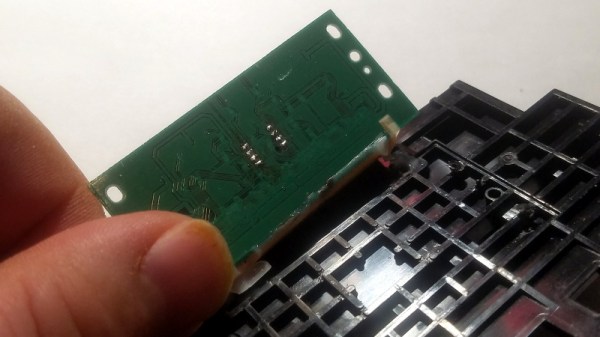
A image of the backside of the PCB shows a wealth of labeled test points, and we imagine figuring out how to get one of these table markers doing your own bidding wouldn’t be too difficult. Not that we condone you swiping one of these things along with your Quarter Pounder with Cheese. Though we are curious to know just why they need so much hardware to indicate which table to take a particular order to; it seems the number printed on the body of the device would be enough to do that.

This isn’t the first time we’ve taken a peek behind the Golden Arches. From reverse engineering their famous fries to hacking the toys they give out with Happy Meals, there’s more to do at the local McDonald’s than get thrown out of the ball pit again.

Badgelife, The Hardware Demoscene Documentary

Last week, tens of thousands of people headed home from Vegas, fresh out of this year’s DEF CON. This was a great year for DEF CON, especially when it comes to hardware. This was the year independent badges took over, thanks to a small community of people dedicated to creating small-run hardware, puzzles, and PCB art for thousands of conference-goers. This is badgelife, a demoscene of hardware, and this is just the beginning. It’s only going to get bigger from here on out.

We were lucky enough to sit down with a few of the creators behind the badges of this year’s DEF CON and the interviews were fantastic. Right here is a lesson on electronic design, manufacturing, and logistics. If you’ve ever wanted to be an engineer that ships a product instead of a lowly maker that ships a product, this is the greatest classroom in the world.

Continue reading “Badgelife, The Hardware Demoscene Documentary”

8087's -5V bias charge pump circuit

How The 8087 Coprocessor Got Its Bias

Most of us have been there. You build a device but realize you need two or more voltages. You could hook up multiple power supplies but that can be inconvenient and just not elegant. Alternatively, you can do something in the device itself to create the extra voltages starting with just one. When [Ken Shirriff] decapped an 8087 coprocessor to begin exploring it, he found it had that very problem. It needed: +5 V, a ground, and an additional -5 V.

His exploration starts with a smoking gun. After decapping the chip and counting out all the bond wires going to the various pads, he saw there was one too many. It wasn’t hard to see that the extra wire went to the chip’s substrate itself. This was for providing a negative bias to the substrate, something done in some high-performance chips to get increased speed, a more predictable transistor threshold voltage, and to reduce leakage current. Examining where the bond wire went to in the circuitry he found the two charge pump circuits shown in the banner image. Those worked in alternating fashion to supply a -5 V bias to the substrate, or rather around -3 V when you take into account voltage drops. Of course, he also explains the circuits and dives in deeper, including showing how the oscillations are provided to make the charge pumps work.

If this is anything like [Ken’s] previous explorations, it’ll be the first of a series of posts exploring the 8087. At least that’s what we hope given how he’d previously delighted us with a reverse engineering of the 76477 sound effects chip used in Space Invaders and then went deeper to talk about integrated injection logic (I2L) as used in parts of the chip.

Multi-switch Useless Box Is Useless In Multiple Ways

We’ve probably all seen (and built) a useless box, in which you flip a switch that activates a servo that pops out a finger and flips the switch off. [Coffeman500] decided to take this a step further by building a useless box with multiple switches. Flip one, the finger pops out to flip it back. Flip several switches, and the finger pops out and flips each back in turn.

It’s a smart build that [coffeeman500] says is his first electronics build. The compulsively switching brain of this is an ATmega328 driving an A4988 stepper motor driver, with one stepper moving the finger mechanism and the other moving the finger along a rail to reach each switch in turn. [Coffeeman500] has released the complete plans for this wonderful waste of time, including 3D models for the box and mechanism, plus the code. Redditors are already planning bigger and more useless designs with more switches, a pursuit that we fully support.

Continue reading “Multi-switch Useless Box Is Useless In Multiple Ways”

Arcade Inspired Halloween Candy Dispenser

The days are getting shorter and the nights are a little cooler, which can only mean one thing: it’s officially time to start devising the trials you’ll put the neighborhood children through this Halloween. For [Randall Hendricks], that means building a new candy dispensing machine to make sure the kids have to work for their sugary reward. After all, where’s the challenge in just walking up and taking some candy from a bowl? These kids need to build character.

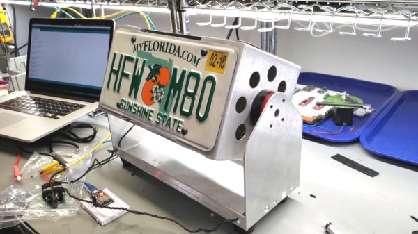
[Randall] writes in to share his early work on this year’s candy contraption which he’s based on a popular arcade game called “Goal Line Rush”. In this skill based game a disc with various prizes spins slowly inside the machine, and the player has a button that will extend an arm from the rear of the disc. The trick is getting the timing right to push the prize off the disc and into the chute. Replace the prizes with some empty calorie balls of high fructose corn syrup, and you get the idea.

There’s still plenty of time before All Hallows’ Eve, so the machine is understandably still a bit rough. He hasn’t started the enclosure yet, and at this point is still finalizing the mechanics. But this early peek looks very promising, and in the video after the break you can see how the machine doles out the goodies.

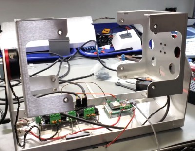
The disc is rotated by a high torque motor, and the aluminum extrusion arm is actuated with a gear motor and custom chain drive. Some 3D printed hardware, a couple limit switches, and a pair of relays make for a fairly straightforward way of pushing the rod out when the player presses the button on the front of the cabinet.

Considering how his previous Mario-themed candy dispenser came out, we doubt this new machine will fail to impress come October. The neighborhood kids should just count themselves lucky he’s not using his creativity to terrorize them instead.

Continue reading “Arcade Inspired Halloween Candy Dispenser”

Build Your Own Linux Single Board Computer

We are fortunate enough to have a huge choice of single-board computers before us, not just those with a bare-metal microcontroller, but also those capable of running fully-fledged general purpose operating systems such as GNU/Linux. The Raspberry Pi is probably the best known of this latter crop of boards, and it has spawned a host of competitors with similarly fruity names. With an entire cornucopia to choose from, it takes a bit more than evoking a berry to catch our attention. The form factors are becoming established and the usual SoCs are pretty well covered already, show us something we haven’t seen before!

[Marcel Thürmer] may have managed that feat, with his Blueberry Pi. On the face of it this is just Yet Another SBC With A Fruity Pi Name, but what caught our attention is that unlike all the others, this is one you can build yourself if you want. It’s entirely open-source, but it differs from other boards that release their files to the world in that it manages to keep construction within the realm of what is possible on the bench rather than the pick-and-place. He’s done this by choosing an Alwinner V3, an SoC originally produced for the action camera market that is available in a readily-solderable TQFP package. It’s a choice that has allowed him to pull off another constructor-friendly feat: the board is only two layers, so it won’t break the bank to have it made.

It’s fair to say that the Allwinner V3 (PDF) isn’t the most powerful of Linux-capable SoCs, but it has the advantage of built-in RAM to avoid more tricky soldering. With only 64Mb of memory, it’s never going to be a powerhouse, but it does pack onboard Ethernet, serial and parallel camera interfaces, and audio as well as the usual interfaces you’d expect. There is no video support on the Blueberry Pi, but the chip has LVDS for an LCD panel, so it’s not impossible to imagine something could be put together. Meanwhile, all you need to know about the board can be found on its GitHub repository. There is no handy OS image to download, u-boot instructions are provided to build your own. We suspect if you’re the kind of person who is building a Blueberry Pi though this may not present a problem to you.

We hope the Blueberry Pi receives more interest, develops a wider community, and becomes a board with a solid footing. We like its achievement of being both a powerful platform and one that is within reach of the home constructor, and we look forward to it being the subject of more attention.

3D Printers Get A Fuel Gauge: Adding A Filament Scale To OctoPrint

It seems a simple enough concept: as a 3D printer consumes filament, the spool becomes lighter. If you weighed an empty spool, and subtracted that from the weight of the in-use spool, you’d know how much filament you had left. Despite being an easy way to get a “fuel gauge” on a desktop 3D printer, it isn’t something we often see on DIY machines, much less consumer hardware. But with this slick hack from [Victor Noordhoek] as inspiration, it might become a bit more common.

He’s designed a simple filament holder which mounts on top of an HX711 load cell, which is in turn connected to the Raspberry Pi running OctoPrint over SPI. If you’re running OctoPrint on something like an old PC, you’ll need to use an intermediate device such as an Arduino to get it connected; though honestly you should probably just be using a Pi.

On the software side, [Victor] has written an OctoPrint plugin that adds a readout of current filament weight to the main display. He’s put a fair amount of polish into the plugin, going through the effort to add in a calibration routine and a field where you can enter in the weight of your empty spool so it can be automatically deducted from the HX711’s reading.

Hopefully a future version of the plugin will allow the user to enter in the density of their particular filament so it can calculate an estimate of the remaining length. The next logical step would be adding a check that will show the user a warning if they try to start a print that requires more filament than the sensor detects is currently loaded.

This is yet another excellent example of the incredible flexibility and customization offered by OctoPrint. If you’re looking for more reasons to make the switch, check out our guide on using OctoPrint to create impressive time lapse videos of your prints, or how you can control the printer from your mobile device.