While most people are satisfied with a calculator application on their smartphone these days, there’s still something to be said for the old fashioned desk calculator. Maybe it’s the fact the batteries last long enough that you can’t remember the last time you changed them, or the feel of physical buttons under your fingers. It could even be the fact that it keeps your expensive smartphone from needing to sit out on the workbench. Whatever the reason, it’s not uncommon to see a real-life calculator (or two) wherever solder smoke tends to congregate.
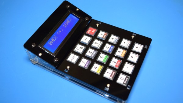
Which is precisely the idea behind this DIY calculator kit. Available from the usual overseas retailers for about $15 USD, it has some hobbyist-oriented features such as the ability to decode resistor color bands, convert hexadecimal numbers, and calculate resistor values for driving LEDs. If you’re going to keep a knock-around calculator on your bench, why not build the thing yourself?
Given the dual nature of this product, a DIY electronics kit and a functional desk calculator for electronic hobbyists, it seems only appropriate to review both aspects of it individually. Which is good, since there may be more to this product than just the sum of its parts.
Continue reading “Review: Calculator Kit Is Just A Few Hacks From Greatness”