Finding it hard to get into the holiday spirit this year? Maybe you just need a timely project to light up the evenings until Santa (or Krampus) pays your house a visit. Whoever visits this season, delight or distract them with a 3D printed tree featuring embedded RGB LEDs.
 [MakeTVee] printed this tree in four stages to make it a little bit easier to wire everything up. Each stage has six LEDs embedded in a 5mm transparent layer at the bottom. The top stage has a second color change to make a tree topper that holds a single LED. The color change feature in PrusaSlicer 2.0 made it easy to pause the print, insert the wired-up LEDs, and resume seamlessly in green filament. There’s a hidden base of what appears to be appropriately delicious cinnamon filament that holds the Trinket M0 and the power switch.
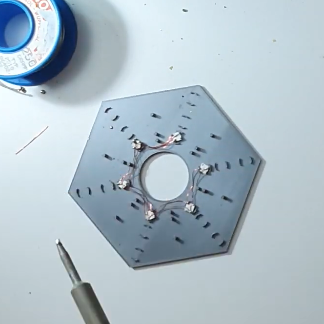
This lil’ tree looks great, especially considering how fiddly and nerve-wracking the wiring and assembly must have been. [MakeTVee] made it easier on himself with a printed wiring stencil that holds the LEDs in their star formation while he solders them up with magnet wire (a solid choice in our book). He thoughtfully included that stencil in the files which are up on the Prusa site. Dim the lights, grab a hot beverage, and check out [MakeTVee]’s build video after the break.
If you want a holiday hack that people can play with, invite them to paint your addressable tree.