Desktop Weather Monitor Leaves Nothing To Chance

[Mirko Pavleski] has put together a little weather station for himself that combines Internet-sourced forecasts with physical sensor data to give him a complete view of his local conditions. There’s no shortage of weather applications for our smartphones and computers that will show us the current local conditions and the forecast for the next couple of days. It’s so easy to pull weather data from the various APIs out there that you even see the functionality “baked in” to different gadgets these days. Of course, you can dig through every weather API in the world and not find the temperature and humidity inside your office; for that, you need your own sensors.

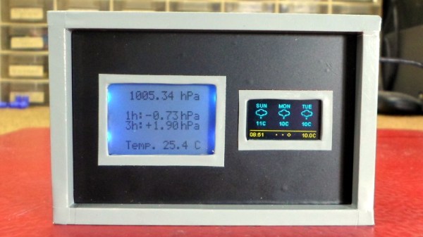
[Mirko] took a somewhat unconventional approach by essentially building two totally separate weather devices and packing them into one enclosure, which gives the final device a rather unique look thanks to the contrasting display technologies used.

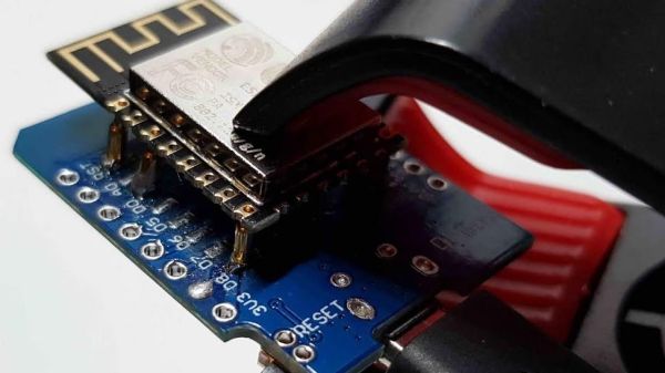
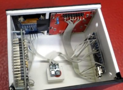
Local conditions are detected by an Arduino Nano connected to a BMP180 sensor and displayed on a Nokia 5110 LCD. The screen shows not only real-time temperature and barometric pressure, but the change in pressure over the last several hours. The three-day forecast, on the other hand, is provided by a NodeMCU ESP8266 development board connected to the increasingly ubiquitous 0.96 inch OLED.

If you’re not into the whole duality thing and would rather do it all on the same device, you might be interested in one of the ESP8266 weather monitors we’ve seen in the past.

Breakout Board Becomes Pogo Pin Programmer

Making a programming jig becomes exponentially more difficult after two pins and who would even consider building one if they were not setting up more than twenty boards? If it were easy for novices to construct jigs, we might all have a quiver of them on the shelf next to our microprocessors. Honestly, a tackle box full of homemade programming fixtures sounds pretty chic. The next advantage to ditching the demo boards is that bare processors take up less room and don’t draw power for unnecessary components like unused voltage regulators and LEDs. [Albert David] improves the return-on-time-investment factor by showing us how to repurpose a WeMos board to program a bare ESP8266 module.

[Albert]’s concept can apply to many other surface-mount chips and modules. The first step is to buy a demo board which hosts a programmable part and remove that part. Since you’ve exposed some solder pads in the process, put pogo pins in their place. Pogo pins are small spring-loaded probes that can be surface mounted or through-hole. We’ve used them for programming gorgeous badges and places where the ESP8266 has already been installed. When you are ready to install your software, clamp your Franken-porcupine to the controller and upload like normal. Rinse, wash, repeat. We even get a view of the clamp [Albert] uses.

DIY Button Matrix Lights Up And Speaks I2C

[David Johnson-Davies] always wanted an illuminated button matrix for projects, but cost was never very friendly. That all changed when he discovered a cheap source of illuminated pushbuttons on Aliexpress, leading to this DIY 4×4 illuminated button matrix design which communicates over I2C. The button states can be read independently of setting the light pattern, and an optional interrupt signal gets pulled low whenever there is a change detected. Not bad for one PCB plus about $10-worth in components!

The device uses every single pin on an ATtiny88, and because each button gets its own pin the keypresses can be detected with pin-change interrupts. The state reporting of buttons over I2C is unambiguous, even when multiple buttons are pressed simultaneously. A simple protocol provides all the needed functionality, and all connections are brought to the board’s edge to allow for easily tiling multiple panels.

The GitHub repository contains the code and PCB files and [David] helpfully shared the board files to OSH Park and PCBWay for easy ordering. In addition, he provides two demos (Tacoyaki and Tacoyaki+) which are games related to the classic Lights Out to show off the matrix.

Building An ESP8266 Game System With MicroPython

After a seemingly endless stream of projects that see the ESP8266 open doors or report the current temperature, it can be easy to forget just how powerful the little WiFi-enabled microcontroller really is. In fact, you could argue that most hackers aren’t even scratching the surface of what the hardware is actually capable of. But that’s not the case for [Brian Wagner] and his students from the Kentucky Country Day School.

Their project, the GamerGorl, is a completely custom handheld game system running on a Wemos D1 Mini development board. The team’s PCB, which was developed over several iterations, is essentially a breakout board which allows them to easily connect up peripheral devices. Given the low total component cost of the GamerGorl and relative simplicity of its construction, it looks like a phenomenal project for older STEM students.

Beyond the ESP8266 board, the GamerGorl features a SSD1106 1.3″ OLED display, a buzzer for sound effects, two tactile buttons, and an analog joystick originally intended for an Xbox controller. Around the backside there’s a WS2812B RGB LED strip that’s at least partially for decoration, but it’s also actively used in some of the games such as the team’s take on Simon.

Even if you aren’t in the market for a portable game system, the GameGorl does provide an interesting case study for MicoPython applications on the Wemos D1 Mini. Browsing through the team’s source code as well as the helpful hints that [Brian] gives about getting the software environment up and running could be useful if you’re looking to expand your ESP8266 programming repertoire. We’d also love to see this device running the “ESP Little Game Engine” we covered recently.

Continue reading “Building An ESP8266 Game System With MicroPython”

An Impeccably Designed High-Speed LED Flash

If you want to take a picture of something fast, and we mean really fast, you need to have a suitably rapid flash to illuminate it. A standard camera flash might be good enough to help capture kids running around the back yard at night, but it’s not going to do you much good if you’re trying to get a picture of a bullet shattering a piece of glass. For that you’ll need something that can produce microsecond flashes, allowing you to essentially “freeze” motion.

You can buy a flash that fast, but they aren’t common, and they certainly aren’t cheap. [td0g] thought he could improve on the situation by developing his own microsecond flash, and he was kind enough to not only share it with the world, but create a fantastically detailed write-up that takes us through the entire design and construction process. Even if you aren’t in the market for a hyper-fast flash for your camera, this is a fascinating look at how you can build an extremely specialized piece of gear out of relatively common hardware components.

So what goes into a fast LED flash? Rather unsurprisingly, the build starts with high-quality LEDs. After some research, [td0g] went with an even dozen CREE CXA2530 arrays at just shy of $7 USD each. Not exactly cheap, but luckily the rest of the hardware is pretty garden variety stuff, including a ATMega328P microcontroller, some MOSFETs, and a TC4452 driver. He did pack in some monstrous 400 V 10μf capacitors, but has since realized they were considerably overkill and says he would swap them out if doing it all over again.

To make development easier (and less costly, should anything go wrong), [td0g] designed the flash so that the LEDs are arranged in banks of three which can be easily removed or swapped in the 3D printed case. Each trio of LEDs is in a removable “sled” that also holds the corresponding capacitor and MOSFET. Then it was just a matter of getting the capacitors charged up and safely dumping their energy into the banks of LEDs without frying anything. Simple.

At this point, the astute reader is probably thinking that a high speed flash is worthless without an equally fast way of triggering it. You’d be right, but [td0g] already figured that part. A couple years back we covered his incredible ballistic chronometer which is being used as a sensor to fire off his new flash.

Bare Metal Programming With Only Three Buttons

For anyone who’s seen a 1970’s era microcomputer like the Altair 8800 doing its thing, you’ll know the centerpiece of these behemoths is the array of LEDs and toggle switches used as input and output. Sure, computers today are exponentially more capable, but there’s something undeniably satisfying about developing software with pen, paper, and the patience to key it all in.

If you’d like to get a taste of old school visceral programming, but aren’t quite ready to invest in a 40 year old computer, then [GClown25] might have the answer for you. He’s developed a pocket sized “computer” he’s calling the BIT4 that can be programmed with just three tactile switches. In reality it’s an ATMega4809 running C code, but it does give you an idea of how the machines of yesteryear were programmed.

In the video after the break, [GClown25] demonstrates the BIT4 by entering in a simple binary counter program. With a hand-written copy of the program to use as a reference, he steps through the memory addresses and enters in the command and then the value he wishes to operate on. After a few seconds of frantic button pushing, he puts the BIT4 into run mode and you can see the output on the array of LEDs along the top edge of the PCB.

All of the hardware and software is open source for anyone who’s interested in building their own copy, or perhaps just wants to take a peak at how [GClown25] re-imagined the classic microcomputer experience with modern technology. Conceptually, this project reminds us of the Digirule2, but we’ve got to admit the fact this version isn’t a foot long is pretty compelling.

Continue reading “Bare Metal Programming With Only Three Buttons”

This Atomic Pi Eats Other Pis For Lunch

The world is full of single board computers that want a slice of the Raspberry Pi action. Most of them are terrible. But fools and their money, yadda yadda, and there’s a new sucker born every minute. The latest contender to the Raspberry Pi is the Atomic Pi. It’s an x86-based single board computer that costs $35, shipped to your door. Is it worth it? Is it even in the same market as a Raspberry Pi? Or is it just a small budget computer without a box? I have no idea.

With that said, the Atomic Pi comes with an Intel Atom x5-Z8350 with Intel HD Graphics (Cherry Trail). There is 2 GB of DDR3L-16000, 16 GB of eMMC, and an SD slot for storage. Connectivity is a full HDMI port (primary audio out), USB 3.0 and 2.0 ports, a Mediatec RT5572 used for WiFi, a Qualcomm CSR8510 for Bluetooth 4.0, a “Legitimate licensed BIOS”, and a real-time clock. Overall, you’re looking at a top-of-the-line tablet computer from four years ago. One that would run Windows.

To use all the features of the Atomic Pi, you will need to buy a $15 breakout board to supply power to the board, and use a large industrial power supply, the kind you would normally find bolted to a RepRap or a homemade CNC machine. You will need to supply both 5 V and 12 V to the board if you would like to use the Class D audio amplifier, but if you only want to use audio over HDMI, supplying only 5 V will do. If you want to boot this board, it looks like you’ll need to bring a USB/TTL cable to make everything work. This may be a tough sell to a crowd with zero experience booting a bare Linux system. That said, it runs Nintendo 64 emulators well, which is the only reason people buy Raspberry Pis anyway.

Is the Atomic Pi the single board computer you need? I don’t know. But we’ve got an Atomic Pi on order, and we’re ready to go with a full review when it show up.