Unbricking A 3D Printer The Hard Way: By Writing A Bootloader

There’s a sinking feeling when a firmware upgrade to a piece of equipment goes wrong. We’ve all likely had this happen and  bricked a device or two. If we are lucky we can simply reapply the upgrade or revert to a previous version, and if we’re unlucky we have to dive into a serial debug port to save the device from the junk pile. But what happens when both those routes fail? If you are [Arko], you reverse-engineer the device and write your own bootloader for it.

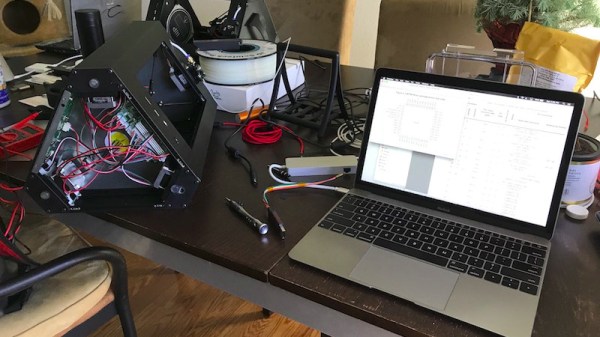
The offending bricked object was a Monoprice MP Mini Delta 3D printer to which he was foolhardy enough to apply new firmware after seeing a friend’s machine taking it without issue. Finding the relevant debug interface on its main PCB he applied the firmware upgrade again, only to realise that in doing so he had overwritten its bootloader. The machine seemed doomed, but he wasn’t ready to give up.

What follows in his write-up is a detailed examination of the boot mechanism and memory map of an ARM Cortex M0 processor as found in the Monoprice’s STM32F070CB. We learn about vector tables for mapping important addresses of interrupts and execution points, and the mechanics of a bootloader in setting up the application it launches. This section is well worth a read on its own, even for those with no interest in bricked 3D printers.

In the end he had a working bootloader to which he appended the application firmware, but sadly when he powered up the printer there was still no joy. The problem was traced to the serial connection between the ARM doing the printer’s business and the ESP8266 running its display. After a brainstorm suggestion with a friend, a piece of code was found which would set the relevant registers to allow it to run at the correct speed.

So after a lot of work that resulted in this fascinating write-up, there was a working 3D printer. He suggests that mere mortals try asking Monoprice for a replacement model if it happens to their printers, but we’re extremely glad he persevered. Without it we would never have had this fascinating write-up, and would be the poorer without the learning experience.

This isn’t the first time we’ve brought you 3D printer bootloader trickery.

The rust language logo being branded onto a microcontroller housing

Baremetal Rust On The Horizon

Rust Programming Langauge has grown by leaps and bounds since it was announced in 2010 by Mozilla. It has since become a very popular language owing to features such as memory safety and its ownership system. And now, news has arrived of an Embedded Devices Working Group for Rust aiming at improving support for microcontrollers.

Rust is quite similar to C++ in terms of syntax, however Rust does not allow for null or dangling pointers which makes for more reliable code in the hands of a newbie. With this new initiative, embedded development across different microcontroller architectures could see a more consistent and standardized experience which will result in code portability out of the box. The proposed improvements include IDE and CLI tools for development and setup code generation. There is also talk of RTOS implementations and protocol stack integration which would take community involvement to a whole new level.

This is something to be really excited about because Rust has the potential to be an alternative to C++ for embedded development as rust code runs with a very minimal runtime. Before Arduino many were afraid of the outcome of a simple piece of code but with rust, it would be possible to write memory-safe code without a significant performance hit. With a little community support, Rust could be a more efficient alternative. We have seen some Rust based efforts on ARM controllers and have covered the basics of Rust programming in the past if you want to get started. Good times ahead for hardware hackers.

On A Quest For The Perfect Numpad

Often times, the only way to get exactly what you want in a device is to just build it yourself. Well, maybe not the only way, but we’ve all certainly told ourselves it was the only way enough that it might as well be true. We don’t know if the DIY imperative felt by [Olav Vatne] to construct his own Bluetooth mechanical number pad was genuine or self-imposed, but in either event, we’re glad he documented the process for our viewing pleasure.

Broken up into three separate posts on his blog, the construction of his custom numpad starts innocently enough with buying a kit from AliExpress. In a rather bizarre twist, the kit arrived assembled, which lead to an arduous period of desoldering to separate all the principle parts [Olav] wanted in the first place. So much for saving time.

Once he freed all the mechanical keys from the kit’s PCB, he went to town hand-wiring the matrix. After testing to make sure all the keys were wired correctly, the matrix got connected to an Adafruit Feather 32u4 Bluefruit. With the electronics sorted, [Olav] moved on to the software side. Here he was able to accomplish one of his primary goals, having a numpad that works over both USB and Bluetooth.

The last step of the process was creating the wooden enclosure. It basically goes together like a picture frame, with special care given to make sure there are appropriate openings in the case for the switches and USB port to pop through without ruining the overall look of the device.

Thanks to cheap USB-capable microcontrollers, hand-made artisan keyboards are now a thing. This project is a nice way to get started with custom input devices, and it only gets better from here.

Racing The Beam On An ATtiny

For the last thirty or so years, the demoscene community has been stretching what is possible on computer systems with carefully crafted assembly and weird graphical tricks. What’s more impressive is hand-crafted assembly code pushing the boundaries of what is possible using a microcontroller. Especially small microcontrollers. In what is probably the most impressive demo we’ve seen use this particular chip, [AtomicZombie] is bouncing boing balls on an ATtiny85. It’s an impressive bit of assembly work, and the video is some of the most impressive stuff we’ve ever seen on a microcontroller this small.

First, the hardware. This is just about the simplest circuit you can build with an ATtiny85. There’s an ISP header, a VGA port with a few resistors, a 1/8″ audio jack driven by a transistor, and most importantly, a 40MHz crystal. Yes, this ATtiny is running far faster than the official spec allows, but it works.

The firmware for this build is entirely assembly, but surprisingly not that much assembly. It’s even less if you exclude the hundred or so lines of definitions for the Boing balls.

The resulting code spits out VGA at 204×240 resolution and sixty frames per second. These are eight color sprites, with Alpha, and there’s four-channel sound. This is, as far as we’re aware, the limit of what an ATtiny can do, and an excellent example of what you can do if you buckle down and write some really tight assembly.

Continue reading “Racing The Beam On An ATtiny”

Love Open Source But Hate People? Get OpenKobold

[Tadas Ustinavičius] writes in to tell us of his latest project, which combines his two great loves of open source and annoying people: OpenKobold. Named after the German mythical spirit that haunts people’s homes, this tiny device is fully open source (hardware and software) and ready to torment your friends and family for up to a year on a CR1220 battery.

The design of the OpenKobold is quite simple, and the open source nature of the project makes this an excellent case study for turning an idea into a fully functional physical object.

Beyond the battery and the buzzer module, the OpenKobold utilizes a PIC12F675, a transistor, and a few passive components. This spartan design allows for a PCB that measures only 25 x 20 mm, making it very easy to hide but fiendishly difficult to try to track down later on.

But the real magic is in the software. The firmware that [Tadas] has written for the PIC not only randomizes how often the buzzer goes off, but how long it will sound for. This makes predicting the OpenKobold with any sort of accuracy very difficult, confounding the poor soul who’s searching their home or office for this maddening little device.

Hackers have a long and storied history of creating elaborate pranks, putting the OpenKobold in very good company. From randomly replaying signals from a remote control to building robotic cardboard burglars, we’ve seen our fair share of elaborate pranks from the community.

Hacking A 30-year-old Russian VFD

Reddit user [InThePartsBin] found some VFDs (Vacuum Fluorescent Displays) on an old PCB on eBay. The Russian boards date from 1987 and have a bunch of through-hole resistors, transistors and a some mystery ICs, plastic wraps around the legs and the top of the tube is held steady by a rubber grommet (the tip itself goes through a hole in a board mounted perpendicular to the main board.) Being the curious kind of person we like, and seeing the boards weren’t too expensive, he bought some in order to play around with to see if he could bring them back to life.

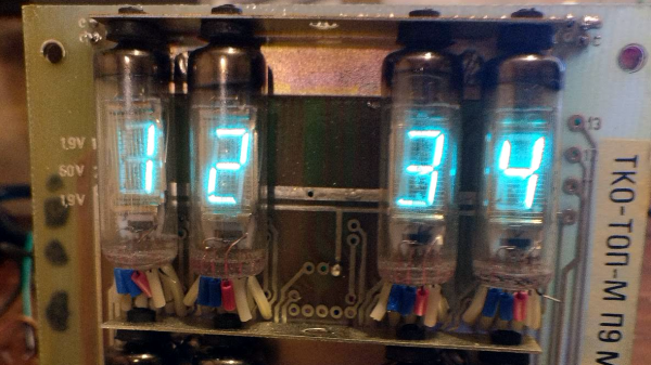
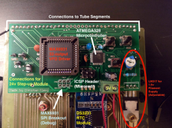
After getting the VFDs lighting up and figuring out the circuitry on the back, [InThePartsBin] decided that a clock was the best thing to build out of it. It was decided that a specialized VFD driver chip was the easiest way to make the thing work, so a MAX6934 was ordered. To give the clock some brains, an ATmega328 was recruited and to keep time, [InThePartsBin] had some DS3231 real-time clock modules left over from a previous project, so they were recruited as well. A daughterboard was designed to sit on the back of the vintage board and hold the ‘328 and the VFD driver chip.

Once [InThePartsBin] soldered on the components it was time to fire it up and send 1’s to the driver to turn on all the segments on all the tubes. Success! The only thing that [InThePartsBin] has left to do is write the code for the clock, but all the segments and tubes are controllable now, so the hardware part is done. There are other VFD clock projects on the site: Check out this one, or this one, and bask in the beautiful steel-blue glow.

Via Reddit.

Tiny Function Generator On The ATtiny85, Complete With OLED

It’s easy to have a soft spot for “mini” yet perfectly functional versions of electronic workbench tools, like [David Johnson-Davies]’s Tiny Function Generator which uses an ATtiny85 to generate different waveforms at up to 5 kHz. It’s complete with a small OLED display to show the waveform and frequency selected. One of the reasons projects like this are great is not only because they tend to show off some software, but because they are great examples of the kind of fantastic possibilities that are open to anyone who wants to develop an idea. For example, it wasn’t all that long ago that OLEDs were exotic beasts. Today, they’re available off the shelf with simple interfaces and sample code.

The Tiny Function Generator uses a method called DDS (Direct Digital Synthesis) on an ATtiny85 microcontroller, which [David] wrote up in an earlier post of his about waveform generation on an ATtiny85. With a few extra components like a rotary encoder and OLED display, the Tiny Function Generator fits on a small breadboard. He goes into detail regarding the waveform generation as well as making big text on the small OLED and reading the rotary encoder reliably. His schematic and source code are both available from his site.

Small but functional microcontroller-based electronic equipment are nifty projects, and other examples include the xprotolab and the AVR-based Transistor Tester (which as a project has evolved into a general purpose part identifier.)