Microgamer Is A Micro:Bit Handheld Console

The BBC micro:bit single board ARM computer aimed at education does not feature as often as many of its competitors  in these pages. It’s not the cheapest of boards, and interfacing to it in all but the most basic of ways calls for a slightly esoteric edge connector. We’re then very pleased to see that edge connector turned from a liability into a feature by [Fabien Chouteau] with his handheld console, he uses micro:bits preprogrammed with different games in the manner of game cartridges in commercial consoles.

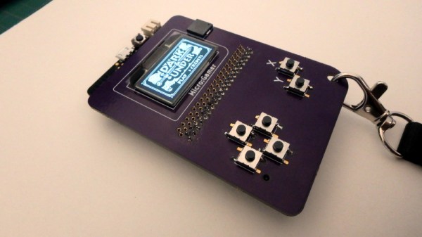
The micro:bit sits in its edge connector on the underside of a handheld PCB above a pair of AAA batteries, while on the other side are an OLED display and the usual set of pushbuttons. It’s a particularly simple board as the micro:bit contains all the circuitry required to support its peripherals.

He’s coded the games using the Arduino IDE with a modified version of the Arduboy2 library that allows him to easily port Arduboy games written for Arduino hardware. It’s a work in progress as there are a few more features to incorporate, but the idea of using micro:bits as cartridges is rather special. There is a video of the console in action, which we’ve placed below the break.

Continue reading “Microgamer Is A Micro:Bit Handheld Console”

x86 emulation running DOS on ESP8266

PC-XT Emulator On ESP8266

Do you remember the simpler times when you had a DOS command line, a handful of commands, and you talked to the hardware through a few BIOS and DOS interrupts? Okay, maybe it was a little limited, but nostalgia doesn’t care. Now [mcuhacker] is working on bringing some of those memories back by getting a PC-XT emulator running on an ESP8266.

For the x86 CPU emulator, he ported Fake86 which is written in C, and created an Arduino IDE environment for it. The MS-DOS 3.3 bootdisk image is stored in flash and is accessed as the A: drive. There’s no keyboard yet but he has 640×200 CGA working with 80×25 characters on a 3.5″ TFT display with the help of a low pass filter circuit. In the video below he shows it booting to the point where it asks for the date.

Continue reading “PC-XT Emulator On ESP8266”

Debugging With Serial Print At 5333333 Baud

Debugging with printf is something [StorePeter] has always found super handy, and as a result he’s always been interested in tweaking the process for improvements. This kind of debugging usually has microcontrollers sending messages over a serial port, but in embedded development there isn’t always a hardware UART, or it might already be in use. His preferred method of avoiding those problems is to use a USB to Serial adapter and bit-bang the serial on the microcontroller side. It was during this process that it occurred to [StorePeter] that there was a lot of streamlining he could be doing, and thanks to serial terminal programs that support arbitrary baud rates, he’s reliably sending debug messages over serial at 5.3 Mbit/sec, or 5333333 Baud. His code is available for download from his site, and works perfectly in the Arduino IDE.

The whole thing consists of some simple, easily ported code to implement a bare minimum bit-banged serial communication. This is output only, no feedback, and timing consists of just sending bits as quickly as the CPU can handle, leaving it up to the USB Serial adapter and rest of the world to handle whatever that speed turns out to be. On a 16 MHz AVR, transmitting one bit can be done in three instructions, which comes out to about 5333333 baud or roughly 5.3 Mbit/sec. Set a terminal program to 5333333 baud, and you can get a “Hello world” in about 20 microseconds compared to 1 millisecond at 115200 baud.

He’s got additional tips on using serial print debugging as a process, and he’s done a followup where he stress-tests the reliability of a 5.3 MBit/sec serial stream from an ATMega2560 at 16 MHz in his 3D printer, and found no missed packets. That certainly covers using printf as a debugger, so how about a method of using the debugger as printf?

These Small PCBs Are Made For Model Rocketry

Model rocketry hobbyists are familiar with the need to roll their own solutions when putting high-tech features into rockets, and a desire to include a microcontroller in a rocket while still keeping things flexible and modular is what led [concretedog] to design a system using 22 mm diameter stackable PCBs designed to easily fit inside rocket bodies. The system uses a couple of 2 mm threaded rods for robust mounting and provides an ATTiny85 microcontroller, power control, and an optional small prototyping area. Making self-contained modular sleds that fit easily into rocket bodies (or any tube with a roughly one-inch inner diameter) is much easier as a result.

The original goal was to ease the prototyping of microcontroller-driven functions like delayed ignition or altimeter triggers in small Estes rockets, but [concretedog] felt there were probably other uses for the boards as well and made the design files available on GitHub. (Thanks!)

We have seen stackable PCBs for rocketry before with the amazingly polished M3 Avionics project, but [concretedog]’s design is much more accessible to some hobbyist-level tinkering; especially since the ATTiny85 can be programmed using the Arduino IDE and the boards themselves are just an order from OSH Park away.

[via Dangerous Prototypes Blog]


Microchip Introduces Tiny Cheap Linux Modules

Linux is in everything these days, and that means designers and engineers are crying out for a simple, easy-to-use module that simplifies the design of building a product to do something with Linux. The best example of this product category would probably be the Raspberry Pi Compute Module, followed by the C.H.I.P. Pro and its GR8 module. There are dozens of boards with Allwinner and Mali chips stuffed inside that can be used to build a Linux product, and the ‘BeagleBone on a Chip’ is a fantastic product if you need Linux and want to poke pins really, really fast.

Now Microchip is rolling out with their answer to the Linux System on Module. The SAMA5D2 is a single chip in a BGA package with a small footprint that runs Linux. It’s capable, it’s cheap, and if you want to put Linux in a project, this is your newest option.

The core product in this new Microchip lineup is the SAMA5D2 SIP, a system in package that puts an ARM Cortex-A5 CPU and DDR2 memory in a single BGA package that, with a cursory examination, looks easy enough to design a PCB around and reflow. There are four chips in this lineup, with 128 Mbit, 512 Mbit, and 1 Gbit of DDR2 memory. The 128 Mbit chip is meant for bare metal and RTOS applications, with the higher memory chips capable of running Linux at least as well as a repurposed router.

This chip is at the core of Microchip’s ATSAMA5D2 SOM, a system on module that adds power management (that only requires a single 3.3V supply), an Ethernet PHY, and boot memory into a single package that’s effectively as hand-solderable as a QFN package. It’s Linux on a Chip, or at least as close as we’ve gotten to such a concept.

Adding Linux to a project is hard, and while there are modules and systems that can do it, we’re always welcoming more options given to designers. While these modules and systems aren’t exactly cheap compared to a beefy ARM microcontroller — the SIP starts at around $9, the SOM is available for $39 in 100-unit quantities — this price is quite low compared to other Linux-on-Modules available.

ESP-01 Bridges The Gap Between IR And WiFi

[Emilio Ficara] dropped us a line recently about his efforts to drag his television and receiver kicking and screaming into the modern era. His TV is old enough that it needs an external tuner, which means it requires two separate remotes to properly channel surf. He wanted to simplify the situation, and figured that while he was at it he might as well make the whole thing controllable over WiFi.

To begin the project, [Emilio] had to capture the IR signals from the two remotes he wanted to emulate. He put together a quick little IR receiver out of parts he had in the junk bin which would connect up to his computer’s microphone port. He then used an open source IR protocol analyzer to capture the codes and decode them into hex values.

As a proof of concept he came up with a little device that combines an ESP-01 with an ATmega88. The ESP-01 runs a minimal web server that receives hex codes as URL query strings. These hex codes are then interpreted by the ATmega88 and sent out over the IR LED. [Emilio] notes that driving the IR LED directly off of the ATmega pin results in fairly low range of around one meter, but that’s good enough for his purposes. If you want to drive the IR LED with more power, you’ll need to add a transistor to do the switching.

Passing the hex code 0x0408 to turn off the TV

Now that he can decode the signals from his original remotes and transmit them over WiFi via his bridge device, he has all the groundwork he needs to come up with a streamlined home entertainment controller. A native application for his smartphone or perhaps a minimal web interface is the last piece of the puzzle.

This project reminds us of a similar attempt at controlling legacy IR devices from a smartphone via Bluetooth. If you’re looking for more information about wrangling IR signals from your microcontroller, this primer from 2013 is still a great look at the subject.

Building An Arduino Smart IC Tester For $25

There’s no question that you can get a lot done with the classic multimeter; it’s arguably the single most capable tool on your bench. But the farther down the rabbit hole of hacking and reverse engineering you go, the more extravagant your testing and diagnostic gear tends to get. For some of us that’s just an annoying reality of the game. For others it’s an excuse to buy, and maybe even build, some highly specialized equipment. We’ll give you one guess as to which group we fall into here at Hackaday.

[Akshay Baweja] is clearly a member of the second group. He’s recently published a guide on building a very slick intelligent Integrated Circuit tester with a total cost of under $25 USD. Whether you’re trying to identify an unknown chip or verifying your latest parts off the slow-boat from China actually work before installing them in your finished product, this $25 tool could end up saving you a lot of time and aggravation.

[Akshay] walks readers through the components and assembly of his IC tester, which takes the form of a Shield for the Arduino Mega 2560. The custom PCB he designed and had manufactured holds the 20 Pin ZIF Socket as well as the 2.4 inch TFT touch screen. The screen features an integrated micro SD slot which is important as you need the SD card to hold the chip database.

With an IC to test inserted into the ZIF socket, the user can have the tester attempt to automatically ID the chip or can manually enter in a part number to lookup. The source code for the Arduino as well as the chip ID database is up on GitHub for anyone looking to add some more hardware to the device’s testing repertoire.

The importance of good test equipment simply cannot be overstated. Between highly specialized gear like this IC tester to classic instruments such as the oscilloscope, your bench is going to be full of weird and wonderful pieces of equipment before too long.

Continue reading “Building An Arduino Smart IC Tester For $25”