Pi Pico Game Boy Flash Cart Gets Slim RP2040 Upgrade

The story for this one starts a few months ago, when [John Green] released his PICO-GB project. His code allowed the Raspberry Pi Pico to stand in for a Game Boy cartridge, complete with a simple text menu that let the user select between ROMs that had been baked into the microcontroller’s firmware. The project was particularly notable for the fact that it was entirely a software solution; while a custom breakout cartridge made for a handy temporary solution, you could have permanently wired the Pico’s pins directly to the Game Boy’s cartridge connector if you wanted to.

PICO-GB running on the full-size Pi Pico

Then in early June, the RP2040 chip that powers the Pi Pico went up for sale in single unit quantities. That opened up the possibility of building the PICO-GB functionality into a cartridge small enough to actually fit inside the Game Boy. So [Martin “HDR” Refseth] got to work creating the slick cartridge PCB you’re seeing now.

The RP2040 is joined by a trio of Texas Instruments TXB0108 level shifters, and there’s a spot for adding a SPI flash chip. The RP2040 supports a maximum of 16 MB of external flash, but given the size of Game Boy games were generally measured in kilobytes, that shouldn’t pose much of a problem.

Looking ahead, the original PICO-GB documentation mentions enhancements like loading ROMs from SD card, as well as hardware additions like a real-time-clock for the more advanced games that supported it. We assume those concepts will become part of [Martin]’s PCB eventually, but these are still early days.

We’ve seen Game Boy cartridge emulation with a microcontroller in the past, but we’re exited to see how the unique capabilities of the Raspberry Pi Foundation’s custom silicon can improve the state-of-the-art.

[Thanks to Itay for the tip.]

Raspberry Pi Pico Oscilloscope

As you dive deeper into the world of electronics, a good oscilloscope quickly is an indispensable tool. However, for many use cases where you’re debugging low voltage, low speed circuits, that expensive oscilloscope is using only a fraction of its capabilities. As a minimalist alternative for these use cases [fhdm-dev] created Scoppy, a combination of firmware for the Raspberry Pi Pico and an Android app to create a functional oscilloscope.

As you would expect, the specifications are rather limited, capturing a maximum of 100 kpts at a speed of 500 kS/s shared between the two channels. Without some additional front end circuitry to protect the Pico, the input voltage is limited to 0-3.3 V. Neither the app nor the firmware is open source, and getting access to the second channel and removing ads requires a ~$3 in-app purchase. Even so, we can still think of plenty of practical uses for a ~$7 oscilloscope. If you do decide to add some front-end circuitry to change to voltage range, you can set them in the app, and switch between them by pulling certain GPIO pins high or low. The app has most of the basic oscilloscope features covered, continuous and single shot capture, adjustable trigger settings and a scalable waveform display.

Simple, cheap oscilloscopes like these have their place, but you start to understand why the “real” ones are so expensive when you see what goes into developing a high performance oscilloscope.

Test Your ‘Blue Pill’ Board For A Genuine STM32F103C8 MCU

With the market for STM32F103C8-based ‘Blue Pill’ boards slowly being overrun with boards that contain either a cloned, fake or outright broken chip, [Terry Porter] really wanted to have an easy, automated way to quickly detect whether a new board contains genuine STM32 silicon, or some fake that tries to look the part. After more than a year of work, the Blue Pill Diagnostics project is now ready for prime time.

We have covered those clone MCUs previously. It’s clear that some of those ‘Blue Pill’ boards obviously do not have a genuine STM32 MCU on them, as they do not have the STM32 markings on them, while others fake those markings on the package and identifying can be hard to impossible. Often only testing the MCU’s actual functionality can give clarity on whether it’s a real STM32 MCU.

These diagnostics allow one to test not only the 64 kB of Flash, but also the 64 kB of ‘hidden’ Flash that’s often found on these MCUs (rebadged 128 kB STM32F103 cores). It further checks the manufacturer JDEC code and uses a silicon bug in genuine STM32F1xx MCUs where the BGMCU_IDCODE cannot be read without either SWD or JTAG connected.

Another interesting feature of Blue Pill Diagnostics is using Mecrisp-Stellaris Forth as its foundation, which allows for easy access to a Forth shell via this firmware as well, not unlike MicroPython and Lua, only in a fraction of the Flash required by those. We have previously written about using Mecrisp-Stellaris in your projects.

DOOM Comes To The NRF5340

If you’re looking for a reminder of how powerful the tiny microcontrollers that run our everyday gadgets have become, check out the work impressive work [Audun Wilhelmsen] has done to get DOOM running on the Nordic Semiconductor nRF5340. This is the sort of Bluetooth SoC you’d expect to find in a headset or wireless keyboard, and yet it’s packing a 128 MHz processor that can go head to head with the Intel 486 that the iconic first person shooter recommended you have in your old beige box PC.

That said, porting the open source shooter over to the nRF5340 wasn’t exactly easy. The challenge was getting the game, which recommended your PC have 8 MB back in 1993, to run on a microcontroller with a paltry 512 KB of memory. Luckily, a lot of the data the game loads into RAM is static. While that might have been necessary when the game was running from a pokey IDE hard drive, the nearly instantaneous access times of solid state storage and the nRF5340’s execute in place (XIP) capability meant [Audun] could move all of that over to an SPI-connected 8 MB flash chip with some tweaks to the code.

nRF53 Development board with I2S DAC

In general, [Audun] explains that many of the design decisions made for the original DOOM engine were made with the assumption that the limiting factor would be CPU power rather than RAM. So that lead to things often getting pre-calculated and stored in memory for instant access. But with the extra horsepower of the nRF5340, it was often helpful to flip this dynamic over and reverse the optimizations made by the original developers.

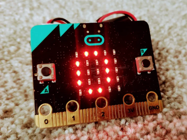
On the hardware side, things are relatively straightforward. The 4.3″ 800×480 LCD display is connected over SPI, and an I2S DAC handles the sound. Bluetooth would have been the logical choice for the controls, but to keep things simple, [Audun] ended up using a BBC micro:bit that could communicate with the nRF5340 via Nordic’s own proprietary protocol. Though he does note that Bluetooth mouse and keyboard support is something he’d like to implement eventually.

If some of the software tricks employed by this hack sounded familiar, it’s because a very similar technique was used to get DOOM running on an IKEA TRÅDFRI light bulb a week or so back. Unfortunately it must have ruffled some feathers, as it was pulled from the Internet in short order. It sounds like [Audun] got the OK from his bosses at Nordic Semiconductor to go public with this project, so hopefully this one will stick around for awhile.

Continue reading “DOOM Comes To The NRF5340”

Review: Inkplate 6PLUS

While the price of electronic paper has dropped considerably over the last few years, it’s still relatively expensive when compared to more traditional display technology. Accordingly, we’ve seen a lot of interest in recovering the e-paper displays used in electronic shelf labels and consumer e-readers from the likes of Amazon, Barnes & Noble, and Kobo. Unfortunately, while these devices can usually be purchased cheaply on the second hand market, liberating their displays is often too complex a task for the average tinkerer.

Enter the Inkplate. With their open hardware ESP32 development board that plugs into the e-paper displays salvaged from old e-readers, the team at e-radionica is able to turn what was essentially electronic waste into a WiFi-enabled multipurpose display that can be easily programmed using either the Arduino IDE or MicroPython. The $99 Inkplate 6 clearly struck a chord with the maker community, rocketing to 926% of its funding goal on Crowd Supply back in 2020. A year later e-radionica released the larger and more refined Inkplate 10, which managed to break 1,000% of its goal.

For 2021, the team is back with the Inkplate 6PLUS. This updated version of the original Inkplate incorporates the design additions from the Inkplate 10, such as the Real-Time-Clock, expanded GPIO, and USB-C port, and uses a display recycled from newer readers such as the Kindle Paperwhite. These e-paper panels are not only sharper and faster than their predecessors, but also feature touch support and LED front lighting; capabilities which e-radionica has taken full advantage of in the latest version of their software library.

With its Crowd Supply campaign recently crossing over the 100% mark, we got a chance to go hands-on with a prototype of the Inkplate 6PLUS to see how e-radionica’s latest hacker friendly e-paper development platform holds up.

Continue reading “Review: Inkplate 6PLUS”

A Mini USB Display For Your PC Desktop

By now it’s likely that most Hackaday readers will be used to USB display adapters, in their most common form channeling DisplayPort over the ubiquitous serial interface. Connecting to projectors and other screens with a laptop becomes a breeze, and gone are the days of “Will my laptop work in the venue” stress for people delivering presentations. [Avra Mitra]’s STM32 tiny monitor may not ascend to these giddy heights, but it does at least live up to the promise of reproducing a desktop onto a small colour LCD hooked up through a USB port.

Not through any DisplayPort wizardry though, instead it relies on a Python script that takes successive screen grabs and streams them through USB to the microcontroller, which in tun puts them on the display. It’s claimed to achieve 6 to 7 frames per second as you can see in the video below, with an admission that there remains a huge scope for improvement.

Notwithstanding its limited utility at the moment, we can see that maybe this idea could have its uses in a very basic display after a few improvements. Meanwhile, more conventional monitors take the established route of pairing a dedicated controller board with an LCD panel.

Continue reading “A Mini USB Display For Your PC Desktop”

Developing A Power Over Ethernet Stack Light

A common sight on factory floors, stack lights are used to indicate the status of machinery to anyone within visual range. But hackers have found out you can pick them up fairly cheap online, so we’ve started to see them used as indicators in slightly more mundane situations than they were originally intended for. [Tyler Ward] recently decided he wanted his build own network controlled stack light, and thought it would double as a great opportunity to dive into the world of Power Over Ethernet (PoE).

Now the easy way to do this would be to take the Raspberry Pi, attach the official PoE Hat to it, and toss it into a nice enclosure. Write some code that toggles the GPIO pins attached to the LEDs in the stack light, and call it a day. Would be done in an afternoon and you could be showing it off on Reddit by dinner time. But that’s not exactly what [Tyler] had in mind.

An early Arduino-based prototype.

He decided to take the scenic route and designed his own custom PCB that combines an Ethernet interface, PoE hardware, and the ESP32 into one compact unit. It’s no great secret that it only takes a few extra components to plug the ESP32 into the network rather than relying on WiFi, but it’s still not something we see done very often by hobbyists. Rarer still is seeing somebody roll their own PoE solution, but thanks to the in-depth documentation [Tyler] has provided for his circuit, that may change in the future.

On the software side [Tyler] has developed a firmware for the ESP32 that supports both Art-Net and RDM protocols, which are subsets of the larger DMX protocol. That means the controller should be compatible with existing software designed for controlling theatrical lighting systems. If you’d rather take a more direct approach, the firmware also sports a web interface and simple HTTP API to provide some additional flexibility.

While it’s exceptionally impressive, not everyone will need such a robust solution. If you just want a quick and easy way to fire up your stack light, a USB controlled relay and some Python can get you where you need to go.