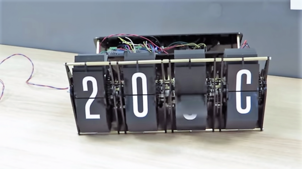
Inductance In PCB Layout: The Good, The Bad, And The Fugly

When current flows through a conductor it becomes an inductor, when there is an inductor there is an electromagnetic field (EM). This can cause a variety of issues during PCB layout if you don’t plan properly, and sometimes we get burned even when we think we have planned for unwanted inductance and the effects that come with them.

When doing high speed logic we need to be able to deliver sudden changes in current to the devices if we want to have proper switching times and logic levels. Unfortunately inductance is usually not a friend in these circumstances as it resists those sudden changes in current. If the high speed devices are driving capacitive loads, which themselves are resisting changes in voltage, even more instantaneous current is needed.

Simply put, inductors resist a change of current, and can act as a low pass filter when in series with the signal or power supply flow. Inductors do this by storing energy in the flux surrounding the conductor. Alternatively capacitors resist a change in voltage (again by storing energy) and can act as a high pass filter when in series with the signal. This makes them a valuable tool in the fight against unwanted inductance in power supply distribution.

In the video below, and the remainder of this article, I’m going to dive into the concept of inductance and how it affects our design choices when laying out circuit boards.

Continue reading “Inductance In PCB Layout: The Good, The Bad, And The Fugly”

Minimal Blinky Project Makes The Chip The Circuit Board

We’ve got a thing for projects that have no real practical value but instead seek to answer a simple yet fundamental question: I wonder if I can do that? This dead-bug style 555 blinky light is one of those projects, undertaken just to see how small a circuit can be. Pretty small, as it turns out, and we bet it can get even smaller.

[Danko]’s minimal circuit is about as small as possible for the DIP version of the venerable 555 chip. The BOM is stripped to the bone: just the chip, three resistors, a capacitor, and an LED. All the discrete components are SMDs in 0805. The chip’s leads are bent around the package to form connections, and the SMDs bridge those “traces” to complete the circuit. [Danko] shows the build in step-by-step detail in the video below. There’s some fairly fine work here, but we can’t help wondering just how far down the scale this could be pushed. We know someone’s made a smaller blinky using a tiny microcontroller, but we’d love to see this tried with the BGA version of the chip which is only 1.4 mm on a side.

Cheers to [Danko] for trying this out and having some fun with an old chip. He seems to have a bit of a thing for the 555; check out this cute robot sculpture that’s built around the chip.

Continue reading “Minimal Blinky Project Makes The Chip The Circuit Board”

This Pinball Game Doesn’t Come In A Box… It Is The Box

Pinball still has that bit of magic that makes it stand out from first person shooters or those screen mashers eating up your time on the bus. The secret sauce is that sense of movement and feedback, and the loss of control as the ball makes its way through the play field under the power of gravity. Of course the real problem is finding a pinball machine. Pinbox 3000 is swooping in to fix that in a creative way. It’s a cardboard pinball machine that you build and decorate yourself.

We ran into them at Maker Faire New York over the weekend and the booth was packed with kids and adults all mashing flippers to keep a marble in play. The kit comes as flat-pack cardboard already scored and printed with guides for assembly which takes about an hour.

The design is quite clever, with materials limited to just cardboard, rubber bands, and a few plastic rivets. Both the plunger that launches the pinball and the flippers are surprisingly robust. They stand up to a lot of force and from the models on display it seems the friction points of cardboard-on-cardboard are the issue, rather than mechanisms buckling under the force exerted by the player.

When first assembled the playfield is blank. That didn’t stop the fun for this set of kits stacked back to back for player vs. player action. There’s a hole at the top of playfields which makes this feel a bit like playing Pong in real life. However, where the kit really shines is in customizing your own game. In effect you’re setting up the most creative marble run you can imagine. This task was well demonstrated with cardboard, molded plastic packaging (which is normally landfill) cleverly placed, plus some noisemakers and lighting effects. The company has been working to gather up inspiration and examples for building out the machines. We love the multiple layers of engagement rolled into Pinbox, from building the stock kit, to fleshing out a playfield, and even to adding your own electronics for things like audio effects.

Check out the video below to see the fun being had at the Maker Faire booth.

Continue reading “This Pinball Game Doesn’t Come In A Box… It Is The Box”

Advanced Techniques For Using Git With KiCAD

For most developers “distributed version control” probably means git. But by itself git doesn’t work very well with binary files such as images, zip files and the like because git doesn’t know how to make sense of the structure of an arbitrary blobs of bytes. So when trying to figure out how to track changes in design files created by most EDA tools git doesn’t get the nod and designers can be trapped in SVN hell. It turns out though KiCAD’s design files may not have obvious extensions like .txt, they are fundamentally text files (you might know that if you’ve ever tried to work around some of KiCAD’s limitations). And with a few tweaks from [jean-noël]’s guide you’ll be diffing and merging your .pro’s and .sch’s with aplomb.

There are a couple sections to the document (which is really meant as an on boarding to another tool, which we’ve gotten to in another post). The first chunk describes which files should be tracked by the repo and which the .gitignore can be configured to avoid. If that didn’t make any sense it’s worth the time learning how to keep a clean repo with the magic .gitignore file, which git will look for to see if there are any file types or paths it should avoid staging.

The second section describes how you can use two nifty git features, cleaning and smudging, to dynamically modify files as they are checked in and out of the repo. [jean-noël]’s observation is that certain files get touched by KiCAD even if there are no user facing changes, which can clutter patch sets with irrelevant changes. His suggested filters prevent this by stripping those changes out as files get checked in. Pretty slick.

Visual Schematic Diffs In KiCAD Help Find Changes

When writing software a key part of the development workflow is looking at changes between files. With version control systems this process can get pretty advanced, letting you see changes between arbitrary files and slices in time. Tooling exists to do this visually in the world of EDA tools but it hasn’t really trickled all the way down to the free hobbyist level yet. But thanks to open and well understood file formats [jean-noël] has written plotgitsch to do it for KiCAD.

In the high(er)-end world of EDA tools like OrCAD and Altium there is a tight integration between the version control system and the design tools, with the VCS is sold as a product to improve the design workflow. But KiCAD doesn’t try to force a version control system on the user so it doesn’t really make sense to bake VCS related tools in directly. You can manage changes in KiCAD projects with git but as [jean-noël] notes reading Git’s textual description of changed X/Y coordinates and paths to library files is much more useful for a computer than for a human. It basically sucks to use. What you really need is a diff tool that can show the user what changed between two versions instead of describe it. And that’s what plotgitsch provides.

plotgitsch’s core function is to generate images of a KiCAD project at arbitrary Git revisions. After that there are two ways to view the output. One is to generate images of each version which can be fed into a generic visual diff tool (UNIX philosophy anyone?). The documentation has an example script to help facilitate setting this up. The other way generates a color coded image in plotgitsch itself and opens it in the user’s viewer of choice. It may not be integrated into the EDA but we’ll take one click visual diffs any day!

Automagic Tool Makes KiCAD Schematic Symbols From PDFs

Last time we talked about a KiCAD tool it was to describe a way to make the zen-like task of manual assembly more convenient. But what about that most onerous of EE CAD tasks, part creation? Home makers probably don’t have access to expensive part library subscriptions or teams of people to create parts for them, so they are left to the tedium of creating them by hand. What if the dream tool existed that could read the darn PDF by itself and make a part? It turns out [Sébastien] made that tool and it’s called uConfig.

uConfig has a pretty simple premise. It scrapes manufacturer datasheets in PDF form, finds what it thinks are diagrams of parts with pin names, functions, etc, and emits the result as parts in a KiCAD library. To aid in the final conversion [Sébastien] added rules engine which consume his custom KiCAD Style Sheets which specify how to categorize pins. In the simple case the engine can string match or use regex to let you specify things like “all pins named VDD[A-C] should be power pins”. But it can also be used to move everything it thinks belongs to “GPIOB” and stick them on the bottom of the created symbol. We could imagine features like that would be of particular use breaking out gigantic parts like a 400 ball BeagleBone on a chip.

Thanks for the tip [arturo182]!

Better Than Original Pong Using Arduino

Games like Pong are legendary, not only in the sense that they are classic hours fun but also that they have a great potential for makers in stretching their learning legs. In an attempt at recreating the original paddle games like Pong and Tennis etc, [Grant Searle] has gone into the depths of emulating the AY-2-8500 chip using an Arduino.

For the uninitiated, the AY-3-8500 chip was the original game silicon that powered Ball & Paddle that could be played on the domestic television. Running at 2 MHz, it presented a 500 ns pixel width and operated to a maximum of 12 Volts. The equivalent of the AY-3-8500 is the TMS1965NLA manufactured by Texas Instruments for those who would be interested.

[Grant Searle] does a brilliant job of going into the details of the original chip as well as the PAL and NTSC versions of the device. This analysis will come in handy should anyone choose to make a better version. He talks about the intricacies of redrawing the screen for the static elements as well as the ball that bounces around the screen. The author presents details on ball traversal, resolution, 2K memory limit and its workarounds.

Then there are details on the sound and the breadboard version of the prototype that makes the whole write-up worth one’s time. If you don’t fancy the analog paddles and would rather use a wireless modern-day touch, check out Playing Pong with Micro:bits

Thanks [Keith O] for the tip.