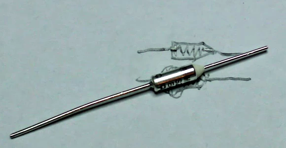
Component Storage Roundup

It’s been suggested that the first self-replicating computer virus was a single IC that eventually expanded into multiple plastic component storage boxes. Organizing components by their values is a huge PITA as well. Here’s some solutions we’ve found:

Photo Boxes

[Mathew] sent in his organization scheme that uses 4×6 photo boxes. Better get those boxes while they’re hot – we can’t remember the last time we used film.

Use a binder

This instructables uses binders for storage. Good for passives, but unless someone can find anti-static bags for a binder, we’ll keep our ICs separate.

The only way to organize resistors

[Johannes] stores his resistors on a sheet of styrofoam. The grid has the first color band on the left side and the second color band on the top. Extremely, extremely clever. We’re wondering why we Radio Shack didn’t come up with this in the 70s. The grid could be laid out on a log scale, though.

If Susan is lazy, why does she do all the work?

[D.C. Boyce] hacked up a couple of lazy susans, built frames out of 2x4s and mounted plastic component drawers on them. The result is probably more space than we’ll ever need. To keep things simple, he wrote a database program to keep track of everything.

All About Accelerometers

If you’ve ever wondered about the use of or theory behind or the use of accelerometers, this tutorial by Love Electronics is a very good resource. In this article, Love takes one through how to hook up an ADXL345 accelerometer and use it with a Netduino processor. Before the subject of hooking everything up is broached, a very good discussion is given on the general theory and operation of accelerometers.

Information is given about installing all the required software and libraries. Additionally, a mini tutorial about writing a “hello” application using the .NET framework is given. Finally, the application gives the [Windows Presentation Foundation] tools necessary to visualize the raw data that the Netduino produces.

One could really start using this processor and accelerometer from scratch with this tutorial and some basic electronics knowledge.  This could add a great new feature to your next robot or allow measurement that couldn’t be done with simpler sensors.

Color Changing EL Wire

All EL wire drivers use a resonator circuit to supply power to the EL wire. It’s an efficient system, but [Paul] noticed that there was some color change when powering different lengths of wire off of the same driver. He realized that this is because of the changing frequency of the resonator circuit, so the only reasonable thing for [Paul] to do was to build a color fading EL wire driver.

The circuit used to drive the wire is very simple. [Paul] used a Teensy board to switch two transistors and produce AC current. This is sent through a step-up transformer which powers the EL wire. It was necessary to use aqua or ‘Tron blue’ EL wire for this build because of the clear wire jacket. Many colors of EL wire have a fluorescent jacket – much like a fluorescent light bulb – that changes the color produced inside the wire to something different. [Paul] says the color change is subtle, but unique.

Of course the build is nothing without a video of the color changing EL wire. Check it out after the break.

Continue reading “Color Changing EL Wire”

DIY Resin Cast Project Box

resin_casting

[Rhys] wrote in to share a custom project box he built from scratch using polyester resin. He states that in New Zealand, he tends to have problems finding the perfect project box. They are typically too big or small to get the job done, so he figured he might as well just build his own to spec.

Using Google SketchUp, he designed his ideal project box, then got busy building wooden molds. He scored some free melamine scraps from a local company, which he used to build the base of his molding rig. Once the inner and outer molds were built, he secured them to his base and mixed up some polyester resin.

A few hours later, he pulled apart his molds and smoothed out his project box with some sandpaper. He drilled and tapped screw holes, then prepared to make a lid and base for the box.

He admits that the process is quite involved, but there is something to be said for building yourself an enclosure made specifically for the project it is going to house. If you are looking to do something similar be sure to check out his blog – he offers up some sound resin casting tips, as well as some pitfalls to avoid.

mobo_salvage

PCB Parts Salvaging Made Easy

Take a moment to think about how many old or damaged computer motherboards you have tossed away over the years. Sure we try to repurpose everything we can, but reclaiming electronic components from complex devices can be overly time consuming if you don’t have the proper means of doing so.

Ideally, if we were to try removing components from a motherboard, an old stove or an unused toaster oven would be great. If you didn’t have either item at your disposal, you could always attack the board with a soldering iron and some braid – but who has the time for that?

[Giorgos Lazaridis] over at PCBHeaven put together a quick video demonstrating his favorite technique for salvaging components after a motherboard has outlived its usefulness. Using a 2000W heat gun, a few hand tools, and couple of metal pans, he had the entire board stripped bare in about 30 minutes time. He talks about some of the best parts he has discovered while salvaging and points out a few hard-to-find items that can be easily obtained by tearing down a motherboard.

Sure his process might not be as easy as inverting a PCB in an oven, but his method is cheap, portable, and takes up very little space.

Keep reading to see [Giorgos’] video demonstration and don’t forget to check out some of the other cool stuff he has done in the past, such as his temperature-controlled soldering station, this acrylic bender, or this bench top function generator.

Continue reading “PCB Parts Salvaging Made Easy”

PC Casemod-inspired Benchtop PSU

benchtop_psu

[Will] had a cheap power supply sitting around, and decided to turn it into a full-featured benchtop PSU. Inspired by some of the other benchtop supplies we have featured in the past, he decided that he wanted his PSU to be more than just a simple-looking box sitting on his work bench. Taking some cues from PC case modding, he put together a unit that is not only very useful, but also quite sharp looking.

The frame of the case was crafted from aluminum angle, while all of the other flat surfaces were made using black polycarbonate. He installed the standard 12v, 3.3v, and 5v terminals you would expect from any benchtop PSU, complete with an LCD display showing the voltages provided by each rail as measured by an Arduino stationed inside the case. Additionally, he installed a variable terminal capable of providing 1.3v-30v, along with its own LCD display. The most unique feature is the multimeter embedded in the front of the case, which makes it virtually impossible to lose.

The case is finished off as you might expect, if you have seen any of his previous work. It features LED lighting on the inside, large fans on either side of the case for optimal air flow, and a pair of machined aluminum handles.

Be sure to check out the quick video below of the PSU being powered on.

Continue reading “PC Casemod-inspired Benchtop PSU”

What Development Board To Use? (Part Two)

We asked for responses to our last Development Board post, and you all followed through. We got comments, forum posts, and emails filled with your opinions. Like last time, there is no way we could cover every board, so here are a few more that seemed to be popular crowd choices. Feel free to keep sending us your favorite boards, we may end up featuring them at a later date!

Continue reading “What Development Board To Use? (Part Two)”