The days of cathode ray tubes, or CRTs, are firmly behind us, and that’s generally a good thing. Display tubes were heavy, bulky and fragile, and needed complicated high-voltage electronics in order to work. But not all of them were actually large: miniature display tubes were also produced, for things like camcorder viewfinders, and [Tavis] from Sideburn Studios decided to turn one of those into a slightly creepy art project.
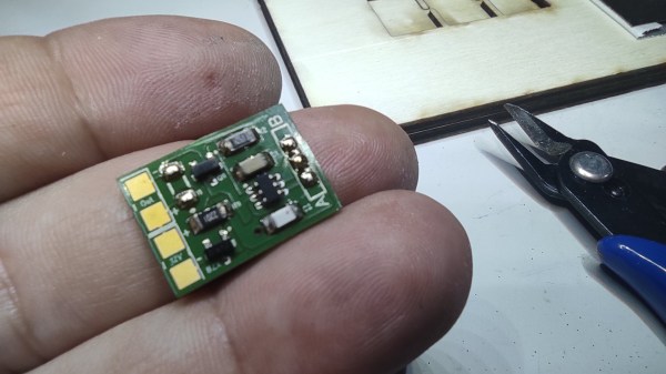
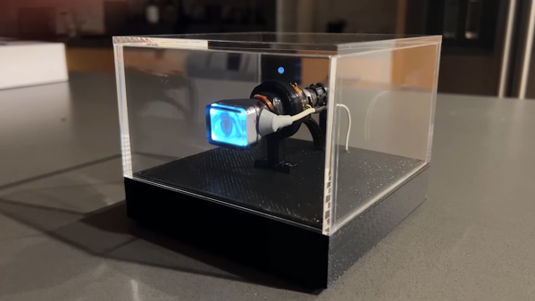
The heart of this build is a one-inch CRT that was salvaged from an RCA video camera. [Tavis] mounted the tiny tube inside an acrylic box on a 3D printed base. Inside that base sits a Raspberry Pi along with a high-voltage driver and a power management board. The Pi continuously plays a video that shows a human eye blinking and looking in various directions. Just an eye, floating in space, looking at the world around it.
The magic is briefly lost when the Pi starts up, because it then shows a microscopic version of the Pi’s standard bootup sequence, but once the thing is running it adds a weird vibe to a room. It actually looks like something you’d find in an avant-garde art exhibition — in the video (embedded below) it’s accompanied by eerie music that gives it an even more unsettling feel. Electronic eyes are always a bit scary, especially when they’re actually looking at you.
Continue reading “This Eye Is Watching You From Its Tiny CRT”