Hinge joints are usually the simplest to use for robotic applications, but if you want motion that looks more organic, rolling joint (or rolling contact) mechanisms are worth a look. [Skyentific] is experimenting with this mechanism and built a 6-degree-of-freedom robotic arm with it.
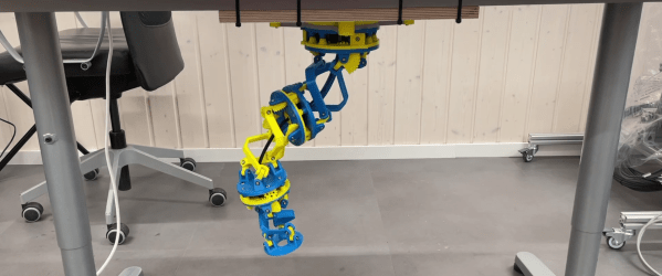
The mechanism doesn’t necessarily need the physical surfaces to roll across each other to work, and you can get to two degrees of freedom with the virtual rolling sphere mechanism. [Skyentific] demonstrates how these work with both cardboard cutouts and 3D printed models. Stacking three of these mechanisms on top of each other, with each stage driven by three Dynamixel servos, the motion seems almost serpentine.
Since the servos are driving the small bottom linkages of each stage, they are operating at a significant mechanical disadvantage. The arm can just barely keep itself upright on top of the table, so [Skyentific] mounted it upside down to the bottom of the table to reduce the load of its weight. With the front stage removed, the load is significantly reduced, and it doesn’t struggle as much.
An interesting advantage of this mechanism is that there is always a straight path down the center for cabling. The length of this line between the two plates remains the same throughout the entire range of motion, so it can also be used to route a rigid drive shaft. This is actually what was done on the LIMS2-AMBIDEX robot to rotate its hand, and is also where saw this mechanism for the first time. Interestingly, that implementation didn’t drive the linkages themselves, but used tension cables around the mechanism. We also see this in a very similar tentacle robot, so it might be a better option.
Continue reading “Rolling Sphere Robotic Arm Seems Serpentine”