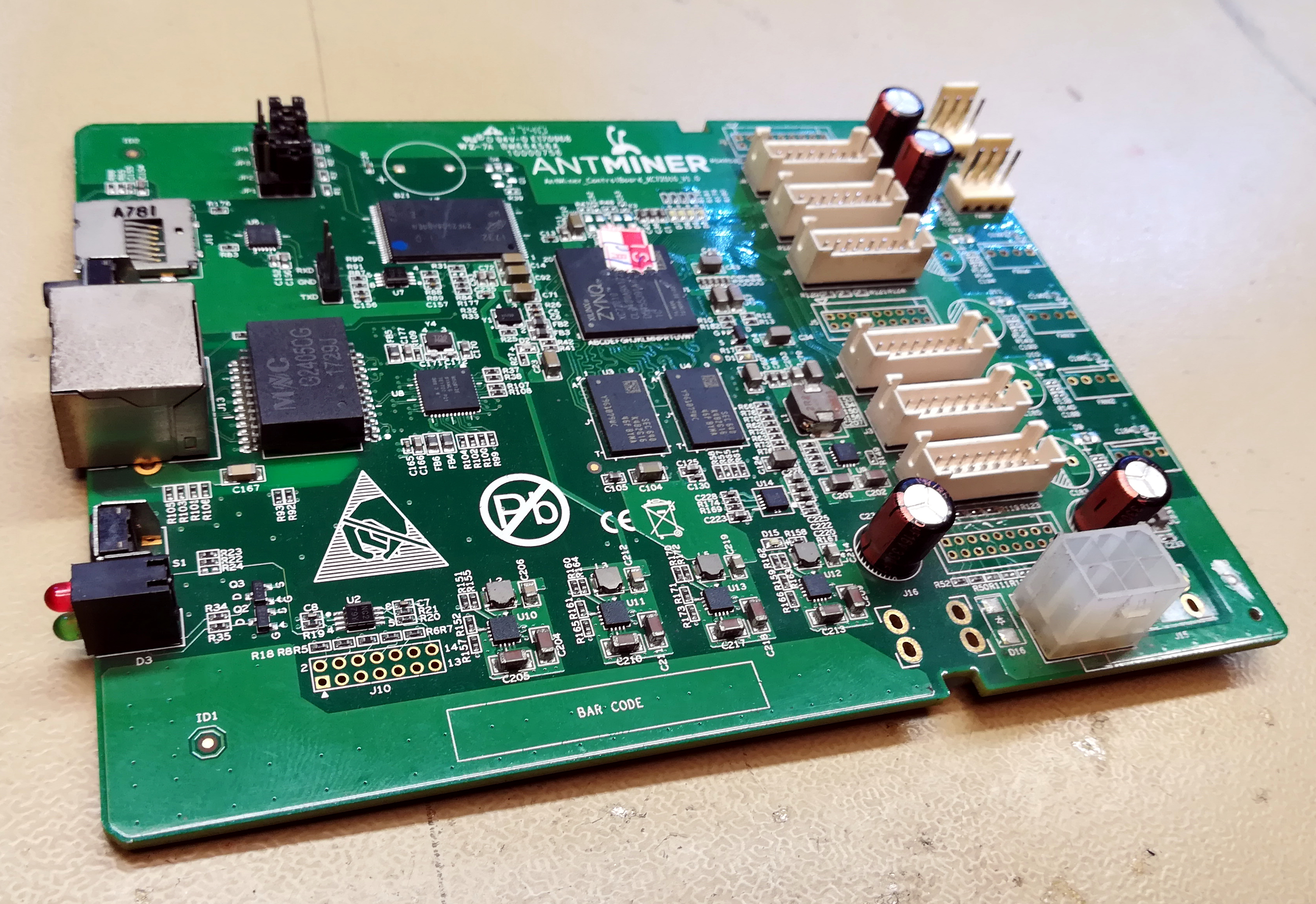
One of the exciting trends in hardware availability is the inexorable move of FPGA boards and modules towards affordability. What was once an eye-watering price is now merely an expensive one, and no doubt in years to come will become a commodity. There’s still an affordability gap at the bottom of the market though, so spotting sub-$20 Xilinx Zynq boards on AliExpress that combine a Linux-capable ARM core and an FPGA on the same silicon is definitely something of great interest. A hackerspace community friend of mine ordered one, and yesterday it arrived in the usual anonymous package from China.
There’s a Catch, But It’s Only A Small One
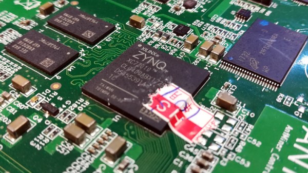
There are two boards to be found for sale, one featuring the Zynq 7000 and the other the 7010, which the Xilinx product selector tells us both have the same ARM Cortex A9 cores and Artix-7 FPGA tech on board. The 7000 includes a single core with 23k logic cells, and there’s a dual-core with 28k on the 7010. It was the latter that my friend had ordered.
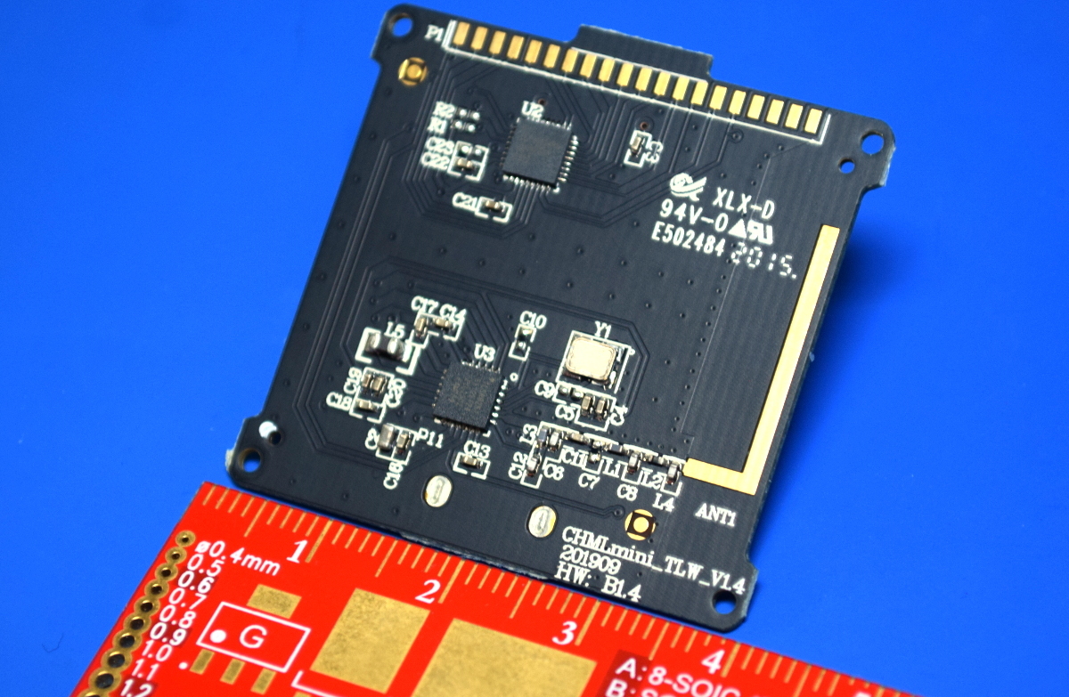
So there’s the good news, but there has to be a catch, right? True, but it’s not an insurmountable one. These aren’t new products, instead they’re the controller boards for an older generation of AntMiner cryptocurrency mining rigs. The components have 2017 date codes, so they’ve spent the last three years hooked up to a brace of ASIC or GPU boards in a mining data centre somewhere. The ever-changing pace of cryptocurrency tech means that they’re now redundant, and we’re the lucky beneficiaries via the surplus market.