Invasion Of The Tiny Magnetic PCB Vises

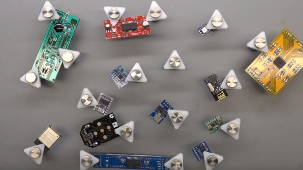
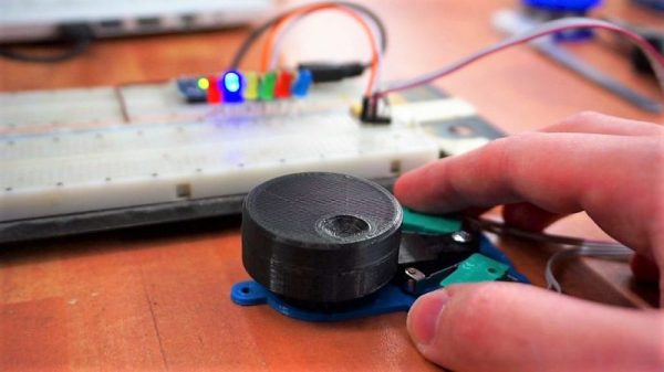
[Proto G] recently wrote in to share a very slick way of keeping tabs on all the tiny PCBs and devices that litter the modern electronics workbench. Rather than a big bulky PCB vise for each little board, he shows how to make tiny grippers with magnetic bases for only a couple bucks each. Combined with a sheet metal plate under an ESD mat, it allows him to securely position multiple PCBs all over his workspace.

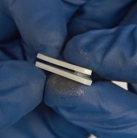
The key to this hack is the little standoffs that are usually used to mount signs to walls. These already have a clamping action by virtue of their design, but the “grip” of each standoff is improved with the addition of a triangular piece of plastic and rubber o-ring.

With the gripping side of the equation sorted, small disc magnets are glued to the bottom of each standoff. With a suitable surface, the magnets are strong enough to stay upright even with a decently large PCB in the jaws.

An especially nice feature of using multiple small vises like this is that larger PCBs can be supported from a number of arbitrary points. It can be difficult to clamp unusually shaped or component-laden PCBs in traditional vises, and the ability to place them wherever you like looks like it would be a huge help.

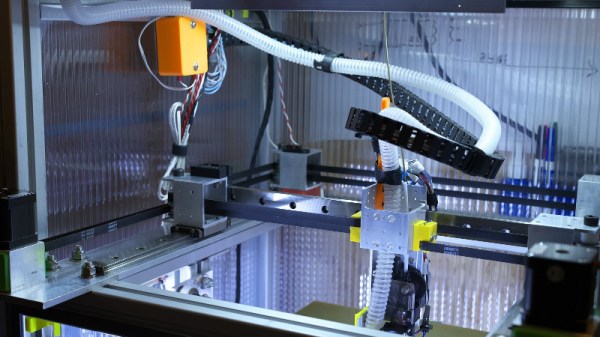
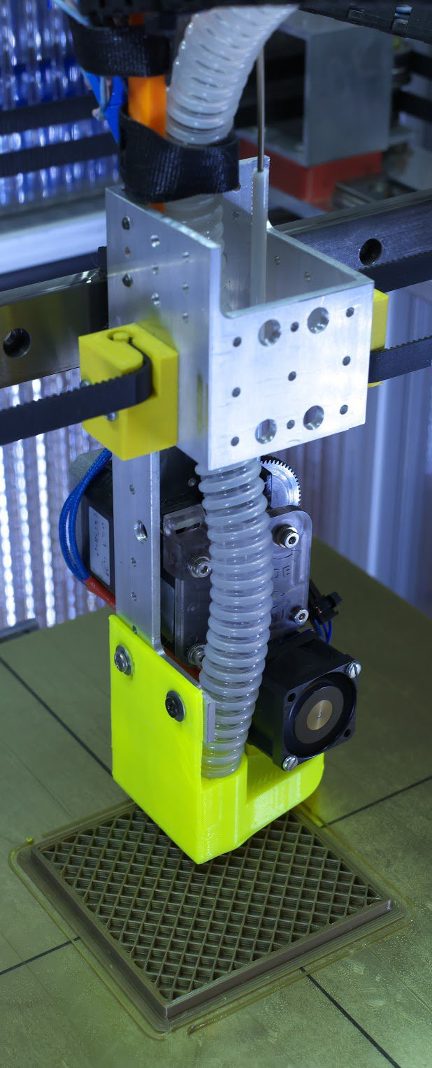
We’ve recently covered some DIY 3D printed solutions for keeping little PCBs where you want them, but we have to say that this solution looks very compelling if you do a lot of work on small boards.

Continue reading “Invasion Of The Tiny Magnetic PCB Vises”

Roll Your Own Rotary Encoders

[miroslavus] hasn’t had much luck with rotary encoders. The parts he has tested from the usual sources have all been problematic either mechanically or electrically, resulting in poor performance in his projects. Even attempts to deal with the deficiencies in software didn’t help, so he did what any red-blooded hacker would do — he built his own rotary encoder from microswitches and 3D-printed parts.

[miroslavus]’s “encoder” isn’t a quadrature encoder in the classic sense. It has two switches and only one of them fires when it turns a given direction, one for clockwise and one for counterclockwise. The knob has a ratchet wheel on the underside that engages with a small trip lever, and carefully located microswitches are actuated repeatedly as the ratchet wheel moves the trip lever. The action is smooth but satisfyingly clicky. Personally, we’d forsake the 3D-printed baseplate in favor of a custom PCB with debouncing circuitry, and perhaps relocate the switches so they’re under the knob for a more compact form factor. That and the addition of another switch on the shaft’s axis to register knob pushes, and you’ve got a perfectly respectable input device for navigating menus.

We think this is great, but perhaps your project really needs a legitimate rotary encoder. In that case, you’ll want to catch up on basics like Gray codes.

Continue reading “Roll Your Own Rotary Encoders”

Retrotechtacular: AM Radios, Core Memory, And Color TV, What Was Hot In Chips In ’73

As part of writing tech stories such as those we feature here at Hackaday, there is a huge amount of research to be done.  We trawl through pages and pages of obscure blogs, videos, and data sheets. Sometimes we turn up resources interesting enough that we file them away, convinced that they contain the nucleus of another story at some point in the future.

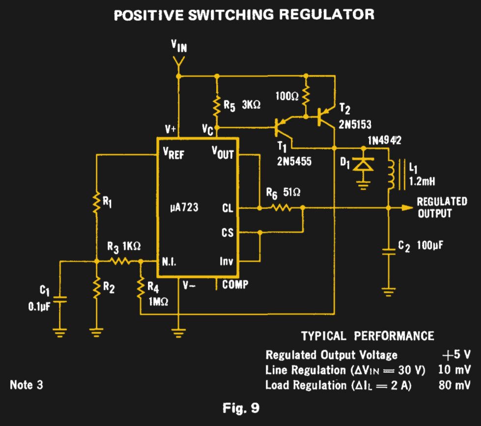
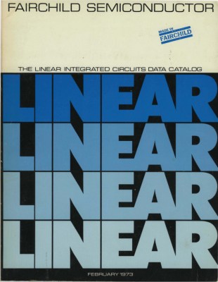
Today’s topic of entertainment is just such a resource, courtesy of the Internet Archive. It’s not a video as we’d often provide you in a Retrotechtacular piece, instead it’s the February 1973 edition of the Fairchild Semiconductor Linear Integrated Circuits Catalog. Books like this one that could be had from company sales representatives were highly prized in the days before universal Internet access to data sheets, and the ink-on-paper datasheets within it provide a fascinating snapshot of the integrated electronics industry as it was 45 years ago.

The first obvious difference between then and now is one of scale, this is a single volume containing Fairchild’s entire range. At 548 pages it wouldn’t have been a slim volume by any means, but given that Fairchild were at the time one of the big players in the field it is unimaginable that the entire range of a 2018 equivalent manufacturer could be contained in the same way. Given that the integrated circuit was at the time an invention barely 15 years old, we are looking at an industry still in relative infancy.

The catalog has a series of sections with familiar headings: Operational amplifiers, comparators, voltage regulators, computer/interface, consumer, and transistor/diode arrays with analog switches. Any modern catalog will have similar headings, and there are even a few devices you will find have survived the decades. The μA741 op-amp (page 64) from its original manufacturer has not yet become a commodity product here, and it sits alongside familiar devices such as the μA7800 series (page 201) or μA723 (page 194) regulators.

Continue reading “Retrotechtacular: AM Radios, Core Memory, And Color TV, What Was Hot In Chips In ’73”

The UA723 As A Switch Mode Regulator

If you are an electronic engineer or received an education in electronics that went beyond the very basics, there is a good chance that you will be familiar with the Fairchild μA723. This chip designed by the legendary Bob Widlar and released in 1967 is a kit-of-parts for building all sorts of voltage regulators. Aside from being a very useful device, it may owe some of its long life to appearing as a teaching example in Paul Horowitz and Winfield Hill’s seminal text, The Art Of Electronics. It’s a favourite chip of mine, and I have written about it extensively both on these pages and elsewhere.

The Fairchild switching regulator circuit. From the μA723 data sheet in their 1973 linear IC databook, page 194 onwards.

For all my experimenting with a μA723 over the decades there is one intriguing circuit on its data sheet that I have never had the opportunity to build. Figure 9 on the original Fairchild data sheet is a switching regulator, a buck converter using a pair of PNP transistors along with the diode and inductor you would expect. Its performance will almost certainly be eclipsed by a multitude of more recent dedicated converter chips, but it remains the one μA723 circuit I have never built. Clearly something must be done to rectify this situation.

Continue reading “The UA723 As A Switch Mode Regulator”

CPAP Hacked Into Super Charged 3D Printer Cooler

Of all the parts on your average desktop 3D printer, the nozzle itself is arguably where the real magic happens. Above the nozzle, plastic is being heated to the precise temperature required to get it flowing smoothly. Immediately below the nozzle there’s a fan blowing to get the plastic cooled back down again. This carefully balanced arrangement of heating and cooling is the secret that makes high quality fused deposition modeling (FDM) printing possible.

But as it turns out, getting the plastic hot ends up being easier than cooling it back down again. The harsh reality is that most of the fans small enough to hang on the side of a 3D printer nozzle are pretty weak. They lack the power to push the volume of air necessary to get the plastic cooled down fast enough. But with his latest project, [Mark Rehorst] hopes to change that. Rather than using some anemic little fan that would be better suited blowing on the heatsink of a Raspberry Pi, he’s using a hacked CPAP machine to deliver some serious airflow.

The brilliance of using a CPAP machine for this hack is two-fold. For one, the machine uses a powerful centrifugal fan rather than the wimpy axial “muffin” fans we usually see on 3D printers. Second, the CPAP pushes air down a lightweight and flexible hose, which means the device itself doesn’t have to be physically mounted to the printer head. All you need is manifold around the printer’s nozzle that connects up to the CPAP hose. This “remote” fan setup means the print head is lighter, which translates (potentially) into higher speed and acceleration.

[Mark] was able to connect the fan MOSFET on his printer’s SmoothieBoard controller up to the brushless motor driver from the CPAP motor, which lets the printer control this monster new fan. As far as the software is concerned, nothing has changed.

He hasn’t come up with a manifold design that’s really optimized yet, but initial tests look promising. But even without a highly optimized outlet for the air, this setup is already superior to the traditional part cooler designs since it’s got more power and gets the fan motor off of the print head.

Getting your 3D printed parts to cool down is serious business, and it’s only going to get harder as printers get faster. We wouldn’t be surprised if fan setups like this start becoming more common on higher-end printers.

An ADS-B Antenna Built From Actual Garbage

With the advent of low-cost software defined radio (SDR), anyone who’s interested can surf the airwaves from the FM band all the way up to the gigahertz frequencies used by geosynchronous satellites for about $20 USD. It’s difficult to overstate the impact this has had on the world of radio hacking. It used to be only the Wizened Ham Graybeards could command the airwaves from the front panels of their $1K+ radios, but now even those who identify as software hackers can get their foot in the door for a little more than the cost of a pizza.

But as many new SDR explorers find out, having a receiver is only half the battle: you need an antenna as well. A length of wire stuck in the antenna jack of your SDR will let you pick up some low hanging fruit, but if you’re looking to extend your range or get into the higher frequencies, your antenna needs to be carefully designed and constructed. But as [Akos Czermann] shows on his blog, that doesn’t mean it has to be expensive. He shows how you can construct a very capable ADS-B antenna out of little more than an empty soda can and a bit of wire.

He makes it clear that the idea of using an old soda can as an antenna is not new, another radio hacker who goes by the handle [abcd567] popularized their own version of the “cantenna” some time ago. But [Akos] has made some tweaks to the design to drive the bar even lower, which he has dubbed the “coketenna”.

The primary advantages of his design is that you no longer need to solder anything or even use any special connectors. In fact, you can assemble this antenna with nothing more than a pocket knife.

You start by cutting the can down to around 68 mm in length, and cutting an “X” into the bottom. Then strip a piece of coax, and push it through the X. The plastic-coated center conductor of the coax should emerge through the bottom of the can, while the braided copper insulation will bunch up on the other side. If you want to make it really fancy, [Akos] suggests cutting a plastic drink bottle in half and using that as a cover to keep water out of the “coketenna”.

How well does it work? He reports performance being very similar to his commercial ADS-B antenna which set him back $45 USD. Not bad for some parts of out the trash.

We’ve covered the math of creating an ADS-B antenna in the past if you’d like to know more about the science of how it all works. But if you just want an easy way of picking up some signals, this “coketenna” and an RTL-SDR dongle will get you started in no time.

Is That Part A Counterfeit? Here Are A Few Pointers

If you order an electronic component, how do you know what it is you are receiving? It has the right package and markings, but have you got the real thing from the original manufacturer or have you got an inferior counterfeit? We hear so much about counterfeit parts, and sometimes the level of effort put in by the fraudsters is so high that from either a visual or electrical standpoint they can be hard to spot.

[Robb Hammond] writes for Aeri, with an extremely interesting guide to some of the cues for spotting a counterfeit semiconductor part. In doing so he gives us something of an insight into the techniques used by the fraudsters.

The first feature of a package to be examined are the indents. Relabeled chips often have their old markings sanded off and a coating applied to simulate the surface of an unmolested chip, and this coating can either obliterate or partially fill any indentations. Using comparison photos we are shown discernable hidden indents, and partially filled indents.

We’re shown textures and paints, and how markings can sometimes be shown as counterfeit by washing with solvent. A Cypress-marked part is found to be a cheaper Altera one under the paint, and other parts are shown with misaligned markings and markings placed over indents. Wildly varying countries of origin are claimed while seemingly retaining the same batch codes, an impossibility confirmed by manufacturers.

If you order your parts from legitimate distributors then it’s likely that what you receive will be the genuine article. However with the popularity of online auction sites and online bazaars the possibility has become ever more likely of being left with a counterfeit. Knowing some of these tips might just make the difference between the success or failure of your work, so it’s an interesting read.

Have you had any dodgy parts on your bench? Tell us about them in the comments. Meanwhile, it’s a subject we’ve covered before.

Via Hacker News.