One of the most annoying things about keyboard and mouse input has got to be the need to constantly switch between the two. Ever wish there was a single solution that combined them with elegance? Then you should definitely check out [lemosbor]’s Lapa keyboard, where the right half includes a mouse sensor.
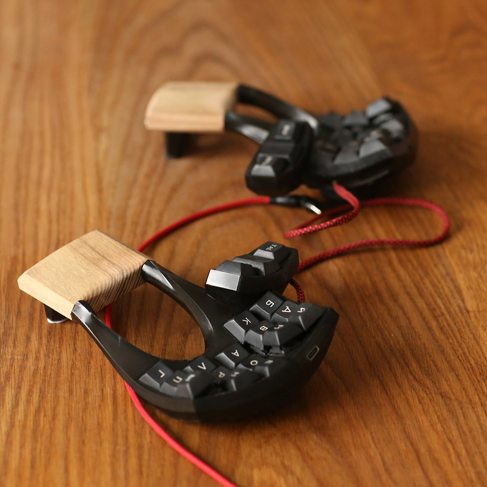
Let me just say that I love the look of this keyboard, and I don’t normally like black and brown together. But that oak — that oak is classy, and it looks good with the resin-and-varnish case. If you can handle a 36-key board — I myself cannot — then this would probably be a game changer. There are even slots for your palms to breathe.
Unfortunately it’s not open source, but a girl can dream, right? In the reddit post, [lemosbor] says that they would be interested in selling the next version, provided it’s the final one.
Continue reading “Keebin’ With Kristina: The One With The Keyboard-Mouse”


![A Raspberry Pi-based AVR workstation that uses a Kaypro keyboard and 9" monochrome Apple ][c display.](https://hackaday.com/wp-content/uploads/2024/12/Atari-AVR-workstation.jpg)