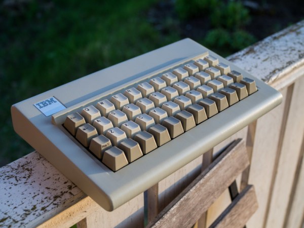
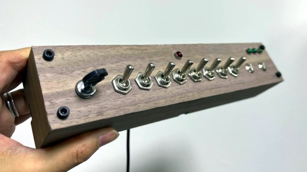
No ARM Printer Driver? Just Write Your Own

When you think of the small machines that print the sticky labels on packages, you might not expect to find a complex printer with its own programming language (ZPL). However, [Dan Pastusek] was looking around online and found a small label printer on everyone’s favorite online warehouse for a great price that suggested it supported ZPL. Unfortunately, [Dan] had big dreams for creating a Raspberry Pi-based print station and found the drivers packaged for this particular printer were not ARM compatible. Not quite content to leave it there, he began to chip away at the layers until he had a working driver.

ZPL, at its core, is just a language describing ASCII commands transmitted over a serial connection. So while the printer showed up as an endpoint, it wasn’t working as the filters (the part of the driver that knows how to convert from a PNG to ZPL) was x86 only. On Linux, printer drivers also have a PPD file that describes what a printer can handle in paper size and other settings. The PPD file for the little printer gave the first clue. In the ShortNickName field, it identifies itself as HPRT N41, which is a popular HP printer. So this little printer must be a clone of a printer in that family. Notably, they don’t support ZPL. Instead, the HPRT series support TSPL, another printer language developed by TSC.

This presented a problem as the shipping service that provided the labels that [Dan] was using offered labels in three formats: PNG, PDF, and ZPL. Currently, it does seem like there’s a TSPL to ZPL converter out there for use, so rather than write his own, he took a shortcut and wrote a rasterizer instead. Initially, he tried to use some sample code that he found, and while he got something to come out of the printer, it was blank. So the next test was to save the raw TSPL output from a filer and cat directly to the serial port. This worked amazingly. Next, he wrote a converter to take a PNG and convert them into the bitmap format the TSPL has. The converter is in Javascript as it runs as part of the webserver that manages the print station. Could it be faster in a different language? Sure. But a different language wouldn’t make the printer any faster.

With the addition of a wireless barcode scanner, it’s satisfying to see the print station up and running. Here at Hackaday, we’re no stranger to seeing folks take apart printers to peel back the software and physical layers that make them up.

Turn On Sarcasm With The Flip Of A Switch

Sarcasm is notoriously difficult to distinguish in online communities. So much, in fact, that a famous internet rule called Poe’s Law is named after the phenomenon. To adapt, users have adopted several methods for indicating implied sarcasm such as the /s tag, but more recently a more obvious sarcasm indicator has appeared that involves random capitalization througout the sarcastic phrase. While this looks much more satisfying than other methods, it is a little cumbersome to type unless you have this sarcasm converter for your keyboard.

The device, built by [Ben S], is based around two Raspberry Pi Pico development boards and sits between a computer and any standard USB keyboard. The first Pi accepts the USB connection from the keyboard and reads all of the inputs before sending what it reads to the second Pi over UART. If the “SaRcAsM” button is pressed, the input text stream is converted to sarcasm by toggling the caps lock key after every keystroke.

For communicating in today’s online world with rapidly changing memes, a device like this is almost necessary for making sure you aren’t misunderstood on whichever popular forum you like to frequent. We don’t know how long this trend will continue, either, but until something else replaces it to more concisely communicate sarcasm we expect it to remain relevant. The build is also a reminder of the various interesting ways that microcontrollers can be programmed to act as keyboards.

Thanks to [ted yapo] for the tip!

Reverse Engineering The NeXT Computer Keyboard Protocol

The NeXT computer was introduced in 1988, with the high-end machine finding favor with universities and financial institutions during its short time in the marketplace. [Spencer Nelson] came across a keyboard from one of these machines, and with little experience, set about figuring out how it worked.

The keyboard features a type of DIN connector and speaks a non-ADB protocol to the machine, but [Spencer] wanted to get it speaking USB for use with modern computers. First attempts at using pre-baked software found online to get the keyboard working proved to be unreliable. [Spencer] suspected that the code, designed to read 50 microsecond pulses from the keyboard, was miscalibrated.

Some analysis with an oscilloscope and logic analyzer allowed [Spencer] to figure out the keyboard was communicating with pulses ever 52.74 microseconds, corresponding to a frequency of 18.960 kHz, sending two 9-bit messages at a time. Disassembling the keyboard confirmed these findings – inside was a 455 kHz clock, with the keyboard sending a signal every 24 ticks producing the 18.960 kHz output.

Reworking the initial code found online to work with the actual pulse widths coming from the keyboard got everything humming along nicely. Now, [Spencer] has a nice vintage keyboard with excellent feel that reliably works with modern hardware. We’d call that a win.

If you need more of a fix, be sure to dive into Keebin’ with Kristina, a regular column all about our favorite tactile input devices!

Setup Menu Uses Text Editor Hack

Many embedded devices that require a setup menu will use a USB serial port which you connect to your favorite terminal emulator. But we recently encountered a generic USB knob that did setup using a text editor, like Notepad or even Vim (although that was a bit ugly). A company called iWit makes several kinds of USB knobs which end up in many such products.

These generic USB knobs are normally just plug-and-play, and are used to control your PC’s volume and muting. Some models, like the iWit, the user can configure the mapping within the device. For example, knob rotation can be set to generate up and down arrow keys, and knob press could be ENTER. One could do this kind of mapping on the PC, but many of these USB knobs can do it for you. The crux of the setup is this menu (which you can see in action in the first 30 seconds of the video below).

Continue reading “Setup Menu Uses Text Editor Hack”

A DIY CAD Mouse You Can Actually Build

When you spend a lot of time on the computer doing certain more specialised tasks (no, we’re not talking about browsing cat memes on twitter) you start to think that your basic trackpad or mouse is, let’s say, lacking a certain something. We think that something may be called ‘usability’ or maybe ease-of-use? Any which way, lots of heavy CAD users gush over their favourite mouse stand-ins, and one particularly interesting class of input devices is the Space Mouse, which is essentially patented up-to-the-hilt and available only from 3DConnexion. But what about open source alternatives you can build yourselves? Enter stage left, the Orbion created by [FaqT0tum.] This simple little build combines an analog joystick with a rotary knob, with a rear button and OLED display on the front completing the user interface.

The idea is pretty straightforward; you setup the firmware with the application you want to use it with, and it emits HID events to the connected PC, replacing the mouse or keyboard input. Since your machine will take input from multiple sources, it doesn’t replace your mouse, it augments it. It may not be very accurate for detailed PCB layout work, but for moving around in a 3D view, or dialling in a video edit, this could be a very useful addition to your workstation, so why not give it a try? The wiring is simple, the parts easily found and cheap, and it’s only a few printed parts! This scribe is already printing the plastics right now, if you listen carefully you might be able to make out the sound of the Lulzbot in background.

There are many other takes on this idea, with varying levels of complexity, like this incredible build from [Ahmsville] that sadly doesn’t make the PCBs available openly, and here’s one we covered earlier mashing the expensive 3DConnexion spacemouse into a keeb.

Continue reading “A DIY CAD Mouse You Can Actually Build”

Illustrated Kristina with an IBM Model M keyboard floating between her hands.

Keebin’ With Kristina: The One With The Tri-lingual Typewriter

Isn’t it just fantastic when a project finally does what you wanted it to do in the first place? [Simon Merrett] isn’t willing to compromise when it comes to the Aerodox. His original vision for the keyboard was a wireless, ergonomic split that could easily switch between a couple of PCs. Whereas some people are more into making layout after layout, [Simon] keeps pushing forward with this same design, which is sort of a mashup between the ErgoDox and the Redox, which is itself a wireless version of the ErgoDox.

The Aerodox has three nRF51822 modules — one for the halves to communicate, one for the control half to send key presses, and a third on the receiver side. [Simon] was using two AA cells to power each one, and was having trouble with the range back to the PC.

The NRFs want 3.3 V, but will allegedly settle for 2 V when times are hard. [Simon] added a boost converter to give each a solid 3.3 V, and the Aerodox became reliable enough to be [Simon]’s daily driver. But let’s go back to the as-yet-unrealized potential part.

Continue reading “Keebin’ With Kristina: The One With The Tri-lingual Typewriter”

The threeboard simulator running

Threeboard: Short On Keys, Long On Documentation

As peripherals go, few are hacked on more than keyboards. The layouts, the shapes, the sizes, materials, and even the question of what a keyboard is are all on the table for tinkering. In that vein, [TaylorConor] released his simplified keyboard called the threeboard on GitHub, having only three keys and replicating a full keyboard.

We’ve covered keyboards built with chording in mind, wrapped around coffee cups, and keyboards with joysticks for added speed. So why cover this one? What makes it different? The execution is superb and is a great example to look at next time you’re making a project you want to show off. The keyboard is just three mechanical switches, two 8-bit binary displays (16 LEDs total), three status LEDs, and three LEDs showing the current layer (four layers). The detailed user’s manual explains it all. There is a reliable Atmega32U4 microcontroller and two EEPROM chips at its heart.

Where this project shows off is the testing. It has unit tests, simulated integration tests, and simulated property tests. Since all the code is in C++, unit testing is relatively straightforward. The integration and property tests are via a simulator. Rather than recompiling the code with some new flags, he uses the simavr AVR simulator, which means it simulates the same binary file that gets flashed onto the microcontroller. This approach means the design is tested and debugged via GDB. It’s an incredible technique we’d love to see more of in hobby projects. Marketing speak might call this a “digital twin” but the idea is that you have a virtual version that’s easier to work on and has a tighter iteration loop while being as close as possible to the physical version.

[TaylorConor’s] goal was to create a from-scratch microcontroller project with easy-to-read code, fantastic documentation, and best practices. We think he nailed it. So feel free to run the simulator or jump right into building one for yourself. All the hardware is under a CERN-OHL-P license, and the firmware is under GPLv3.