True Networked KVM Without Breaking The Bank

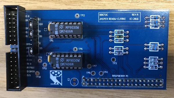
For administering many computers at once, an IP KVM is an invaluable piece of equipment that makes it possible to get the job done over the network without having to haul a keyboard, monitor, and mouse around to each computer. The only downside is that they can get pricey, unless of course you can roll one out based on the Raspberry Pi and the PiKVM image for little more than the cost of the Pi itself.

The video linked below shows how to set all of this up, which involves flashing the image and then setting up the necessary hardware. The build shows an option for using HDMI over USB, but another option using the CSI bus would allow for control over options like video resolution and color that a USB HDMI dongle doesn’t allow for. It also makes it possible to restart the computer and do things like configure BIOS or boot from removable media, which is something that would be impossible with a remote desktop solution like VNC.

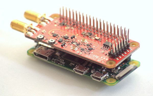
The creator of PiKVM was mentioned in a previous post about the creation of the CSI bus capture card, and a Pi hat based on this build will be available soon which would include options for ATX controls as well. Right now, though, it’s possible to build all of this on your own without the hat, and is part of what makes the Pi-KVM impressive, as well as its very low cost.

Continue reading “True Networked KVM Without Breaking The Bank”

Easy Device Configuration For Your Pi Projects

We’re all familiar with a typical configuration sequence for a new mass-market IoT device. Turn it on for the first time and it exposes a temporary Wi-Fi network, connect to that network and open a Web page for device configuration. Wouldn’t it be useful to be able to incorporate that functionality into your own projects without having to write it yourself! Happily now thanks to [Peter Walsh] you can, with his AppDaemon project for the Raspberry Pi.

At its heart is  a set of Perl scripts that run whatever your software is, then monitor a GPIO. A button press toggling the GPIO stops the application and fires up the access point and web server. Handily the code can all be found in a GitHub repository, and there is a run-through of the features in a video that we’ve placed below the break. It’s not something that will appeal to everybody, but for anyone who has to pass their work onto people who can’t dive into a config file and break out the editor, it should be a particularly useful addition to the armoury.

Continue reading “Easy Device Configuration For Your Pi Projects”

Easy Carrier Board For The Compute Module 4 Shows You Can Do It, Too

The Raspberry Pi Compute Module 4 has got many excited, with a raft of new features bringing exciting possibilities. However, for those used to the standard Raspberry Pi line, switching over to the Compute Module form factor can be daunting. To show just how easy it is to get started, [timonsku] set about producing a quick and dirty carrier board for the module at home.

The Twitter thread goes into further detail on the design of the board. The carrier features HDMI, USB-A and USB-C ports, as well as a microSD slot. It’s all put together on a single-sided copper PCB that [timonsku] routed at home. The board was built as an exercise to show that high-speed signals and many-pin connectors can be dealt with by the home gamer, with [timonsku] sharing tips on how to get the job done with cheap, accessible tools.

The board may look rough around the edges, but that’s the point. [timonsku] doesn’t recommend producing PCBs at home when multi-layer designs can be had cheaply from overseas. Instead, it serves to show how little is really required to design a carrier board that works. Even four-layer boards can be had for under $10 apiece now, so there’s never been a better time to up your game and get designing.

For those eager to learn more about the CM4, we’ve got a full breakdown to get you up to speed!

Adventures In Overclocking: Which Raspberry Pi 4 Flavor Is Fastest?

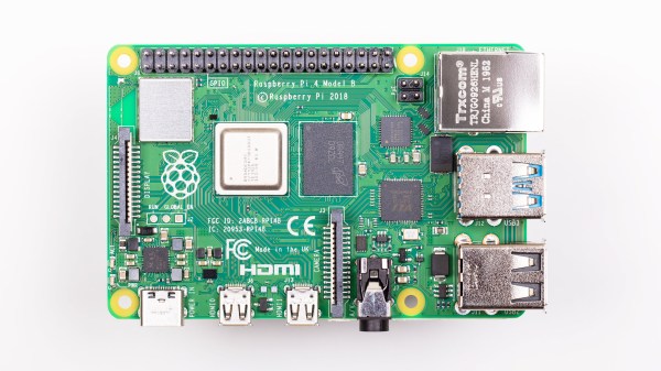
There are three different versions of the Raspberry Pi 4 out on the market right now: the “normal” Pi 4 Model B, the Compute Module 4, and the just-released Raspberry Pi 400 computer-in-a-keyboard. They’re all riffing on the same tune, but there are enough differences among them that you might be richer for the choice.

The Pi 4B is easiest to integrate into projects, the CM4 is easiest to break out all the system’s features if you’re designing your own PCB, and the Pi 400 is seemingly aimed at the consumer market, but it has a dark secret: it’s an overclocking monster capable of running full-out at 2.15 GHz indefinitely in its stock configuration.

In retrospect, there were hints dropped everywhere. The system-on-a-chip that runs the show on the Model B is a Broadcom 2711ZPKFSB06B0T, while the SOC on the CM4 and Pi 400 is a 2711ZPKFSB06C0T. If you squint just right, you can make out the revision change from “B” to “C”. And in the CM4 datasheet, there’s a throwaway sentence about it running more efficiently than the Model B. And when I looked inside the Pi 400, there was this giant aluminum heat spreader attached to the SOC, presumably to keep it from overheating within the tight keyboard case. But there was one more clue: the Pi 400 comes clocked by default at 1.8 GHz, instead of 1.5 GHz for the other two, which are sold without a heat-sink.

Can the CM4 keep up with the Pi 400 with a little added aluminum? Will the newer siblings leave the Pi 4 Model B in the dust? Time to play a little overclocking!

Continue reading “Adventures In Overclocking: Which Raspberry Pi 4 Flavor Is Fastest?”

Trying (And Failing) To Use GPUs With The Compute Module 4

The Raspberry Pi platform grows more capable and powerful with each iteration. With that said, they’re still not the go-to for high powered computing, and their external interfaces are limited for reasons of cost and scope. Despite this, people like [Jeff Geerling] strive to push the platform to its limits on a regular basis. Unfortunately, [Jeff’s] recent experiments with GPUs hit a hard stop that he’s as yet unable to overcome.

With the release of the new Compute Module 4, the Raspberry Pi ecosystem now has a device that has a PCI-Express 2.0 1x interface as stock. This lead to many questioning whether or not GPUs could be used with the hardware. [Jeff] was determined to find out, buying a pair of older ATI and NVIDIA GPUs to play with.

Immediate results were underwhelming, with no output whatsoever after plugging the modules in. Of course, [Jeff] didn’t expect things to be plug and play, so dug into the kernel messages to find out where the problems lay. The first problem was the Pi’s limited Base Address Space; GPUs need a significant chunk of memory allocated in the BAR to work. With the CM4’s BAR expanded from 64MB to 1GB, the cards appeared to be properly recognised and ARM drivers were able to be installed.

Alas, the story ends for now without success. Both NVIDIA and ATI drivers failed to properly initialise the cards. The latter driver throws an error due to the Raspberry Pi failing to account for the I/O BAR space, a legacy x86 feature, however others suggest the problem may lay elsewhere. While [Jeff] may not have pulled off the feat yet, he got close, and we suspect with a little more work the community will find a solution. Given ARM drivers exist for these GPUs, we’re sure it’s just a matter of time.

For more of a breakdown on the Compute Module 4, check out our comprehensive article. Video after the break.

Continue reading “Trying (And Failing) To Use GPUs With The Compute Module 4”

Getting Over 4Gbps Out Of A Compute Module 4

For the average home gamer, good old fashioned Ethernet at 100 Mbit/s is only just starting to become a bottleneck as things like 4K video streaming begin to demand more bandwidth. As always, though, there are those who wish to push the limits of what is possible. [Jeff Geerling] is one such operator, who set out to maximise the network throughput on the Raspberry Pi Compute Module 4. 

The build began by taking advantage of the PCI-Express 2.0 single lane interface on the new Raspberry Pi Compute Module. Hooked up to an Intel four-port Gigabit Ethernet card, and in combination with the onboard Gigabit-E port, [Jeff] was able to get 3.0 Gbit/s out of the setup without too much fuss. However, he wanted more, and set about finding where he was being held back. It turned out that ksoftirqd, a daemon that handles network packets, can only run on one core on the Raspberry Pi 4, and it was getting maxed out at this data rate. Overclocking the CPU helped, getting the max rate up to 3.4 Gbit/s.

Further analysis showed that the onboard interface was only contributing 200 Mbit/s, with the Intel card maxing out at 3.2 Gbit/s. In the case of the latter, this was due to the limits of the PCI-E interface. In the case of the former, however, [Jeff] knew that more was available. The trick turned out to be recompiling the Linux kernel to allow the internal interface to be able to set to use a higher Maximum Transmission Unit. This allows each network transmission to carry more data without extra CPU load. With the internal interface and the external card all set to an MTU of 9000, the Pi was able to spit out a scorching 4.15 Gbit/second. Details of the hack are available on Github for the curious.

It’s a hack that doesn’t offer a lot to the average user, though [Jeff] states he has some interesting applications in mind. He’s also contemplating what can be achieved with a 10 Gbit card, which we can’t wait to see. If you want to learn more about the Compute Module’s features, including a couple of tips for laying out yor own board, check out our review. Video after the break.

Continue reading “Getting Over 4Gbps Out Of A Compute Module 4”

Ethernet Goes To The Ether

Since the ether is an old term for the fictitious space where radio waves propagate, we always thought it was strange that the term ethernet refers to wired communication. Sure, there are wireless devices, but that’s not really ethernet. [Jacek] had the same thought, but decided to do something about it.

What he did is use two different techniques to alter the electromagnetic emission from an ethernet adapter on a Raspberry Pi. The different conditions send Morse code that you can receive at 125 MHz with a suitable receiver.

Practical? Hardly, unless you are looking to exfiltrate data from an air-gapped machine, perhaps. But it does have a certain cool factor. The first method switches the adapter between 10 Mbps and 100 Mbps. The second technique uses a stream of data to accomplish the modulation. The switching method had a range of around 100 meters while the data-based method topped out at about 30 meters. The code is on GitHub if you want to replicate the experiment.

There is plenty of precedent for this sort of thing. In 1976 Dr. Dobb’s Journal published an article about playing music on an Altair 8800 by running code while an AM radio was nearby. We’ve seen VGA adapters forced to transmit data, too.

Continue reading “Ethernet Goes To The Ether”