3D Printed SCARA Arm With 3D Printer Components

One of the side effects of the rise of 3D printers has been the increased availability and low cost of 3D printer components, which are use fill for range of applications. [How To Mechatronics] capitalized on this and built a SCARA robot arm using 3D-printed parts and common 3D-printer components.

The basic SCARA mechanism is a two-link arm, similar to a human arm. The end of the second joint can move through the XY-plane by rotating at the base and elbow of the mechanism. [How To Mechatronics] added Z-motion by moving the base of the first arm on four vertical linear rods with a lead screw. A combination of thrust bearings and ball bearings allow for smooth rotation of each of the joints, which are belt-driven with NEMA17 stepper motors. Each joint has a microswitch at a certain position in its rotation to give it a home position. The jaws of the gripper slide on two parallel linear rods, and are actuated with a servo. For controlling the motors, an Arduino Uno and CNC stepper shield was used.

The arm is operated from a computer with a GUI written in Processing, which sends instructions to the Arduino over serial. The GUI allows for both direct forward kinematic control of the joints, and inverse kinematic control,  which will automatically move the gripper to a specified coordinate. The GUI can also save positions, and then string them together to do complete tasks autonomously.

The base joint is a bit wobbly due to the weight of the rest of the arm, but this could be fixed by using a frame to support it at the top as well. We really like the fact that commonly available components were used, and the link in the first paragraph has detailed instructions and source files for building your own. If the remaining backlash can be solved, it could be a decent light duty CNC platform, especially with the small footprint and large travel area. Continue reading “3D Printed SCARA Arm With 3D Printer Components”

Getting Started With Geometric Algebra For Robotics, Computer Vision And More

[Hugo Hadfield] wrote to let us know about an intriguing series of talks that took place in February of this year at GAME2020, on the many applications of geometric algebra. The video playlist of these talks can be found here along with the first video embedded after the break. For those of us who did not take advanced algebra during university, one can picture geometric algebra (GA) as an extension of vector algebra, adding more algebraic structures.

The essential difference is that GA adds a new vectors product, called the ‘geometric product’. The Cliff’s Notes version is that this is very useful for doing for example transformations, like in 3D spaces. For a quick algebraic introduction to GA for those familiar with vector algebra, the associated biVector website is helpful, from where one can also find additional information, software and other resources on getting started with GA.

These talks will take the viewer through the use of GA with robot kinematics (co-presented by [Hugo]), in astrophysics and AI. Definitely worth a watch, even algebra isn’t one’s strongest points.

Continue reading “Getting Started With Geometric Algebra For Robotics, Computer Vision And More”

Robot Cat Takes Inspiration From Nature

Oftentimes, a project starts with a clean sheet of paper, and we set out wildly sketching towards the goal in our minds. However, it can pay to do your research first, as [Chen Liang] demonstrates with this great robotic cat build.

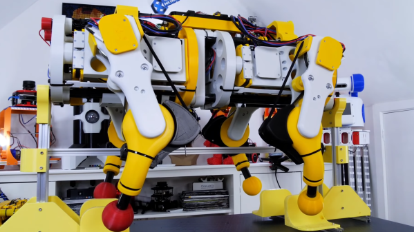
[Liang] began the project after being dissatisfied with existing robot animals they’d seen online. Rather than simply attempt to build a cat from memory, instead, [Liang] decided to first study a real cat to ensure the resulting robot would bear real resemblence to its biological inspiration. [Liang]’s focus was on the skeleton, as replicating the way the real skeleton worked would create a robot with more authentic movement.

Using 3D printed parts and many, many servos, we think [Liang] has done an admirable job at creating a basic robot cat platform. With an ESP32 running the show, the cat can be posed using a web interface to control the servo positions of its various joints. We look forward to future upgrades that enable fluid movement and other capabilities, particularly involving the onboard camera.

It’s not the first robot cat we’ve seen, and it’s likely it won’t be the last. If you’ve got one living in your own lab, drop us a note on the tipline. Video after the break.

Continue reading “Robot Cat Takes Inspiration From Nature”

Lego Ziplining Robot Climbs For Claps

The internet has given us plenty of cool robotics projects, but we don’t think we’ve seen one zipline before. At least not until now.

This cool little ziplining robot is courtesy of the folks over at [Tart Robotics]. As they described it, the robot moves using a 4-bar linkage mechanism with the motor’s torque “transferred to the arm mechanisms through a pair of bevel gears and a worm drive.” Even cooler, the robot is activated by clapping. The faster you clap, the faster the robot moves. That’s sure to wow your friends at your next virtual hacker meetup.

They had to do a bit of custom 3D printing work to get a few of the Lego components to connect with their non-Lego off-the-shelf bits, so that took a bit of time. Specifically, they had some cheap, non-branded DC motors that they used that did not naturally mate with the Lego Technic components used to create the rest of the robot’s body. Nothing a few custom 3D printing jobs couldn’t solve.

It always amazes us what cool contraptions you can put together with a few Lego blocks. What’s your favorite Lego project?

Continue reading “Lego Ziplining Robot Climbs For Claps”

Robotic Worm Uses NinjaFlex Filament

If you think about building a moving machine, you probably will consider wheels or tracks or maybe even a prop to take you airborne. When [nwlauer] found an earthworm in the garden, it inspired a 3D-printed robot that employs peristaltic motion. You can see a video of it moving, below.

The robot uses pneumatics and soft plastic, and is apparently waterproof. Your printer’s feed path has to be pretty rigid to support flexible filament without jamming. There’s also some PVA filament and silicone tubing involved.

Continue reading “Robotic Worm Uses NinjaFlex Filament”

Roller-Based Robot Hand Grasps

In a recent International Conference on Robotics and Automation paper, [Shenli Yaun] and some others from Stanford discuss the design of a roller-based robot hand that has many features that mimic the human hand. The key feature is that each of the three fingers has a roller with a small geared motor.

The rollers allowed the hand to change an object’s orientation without losing its grasp. Of course, this works well with spherical objects like a ball. But the video shows that it can manipulate other items like a 6-sided die, a water bottle, or even a piece of paper. By spreading the fingers it can even hold large objects you wouldn’t expect at first glance.

Continue reading “Roller-Based Robot Hand Grasps”

Linkage Inferring Software Handwaves Away The Hard Stuff

Jokes aside, manually designing linkages that move along specific paths is no easy task. Whether we’re doodling paper sketches or constraining lines in a CAD program, we still need to do the work of actually “imagining” the linkage design. If only there were some sort of tool that would do all that hard imagining work for us! Thankfully, we’re in luck! That’s exactly what researchers [Gen Nishida], [Adrien Bousseau2], and [Daniel G. Aliaga1] at Purdue have done. They’ve designed a software tool that lets us position important bodies in space in particular “key” frames, and then the software simply fills in the linkage for you!

To start the design process, the user inputs a few candidate locations that their solid bodies need to reach in the final linkage path.  From here, these locations get fed to a particle filter. This particle filter seeds thousands of semi-random linkage configurations at small timesteps, selects some of the best-matching ones that most closely approximate the required body locations, removes the lesser-scoring results, re-creates a new set of possible joint configurations based on the best matching ones, and repeats until the tool converges on a linkage that respects our input key frames.

Like a brute force search, this solution takes lots and lots of samples to find a solution, but unlike a brute force search, trials iteratively improve, enabling the software to converge closer and closer to a final solution. Under the hood, the software needs to actually simulate these candidate linkage in order to grade them. It’s in this step that the team wrote in additional checks to remove impossible linkages like self-intersecting joints from this linkage “gene pool” before reseeding them. The result is a tool that does all that trial-and-error scratchwork for you–no brain cycles. For more details, have a peek at their (open access!) paper.

Design software that augments our mechanical design capabilities is a rare gem on these pages, and this one is no exception. If your curious to play with other useful linkages simulating tools, have a go at Linkage Designer. And if you’re in the mood for other tools that fill in the blanks, check out this machine learning algorithm that literally fills in footage between frames in a video feed.

Continue reading “Linkage Inferring Software Handwaves Away The Hard Stuff”